This thread has been locked.

If you have a related question, please click the "Ask a related question" button in the top right corner. The newly created question will be automatically linked to this question.

DP83TC812R-Q1: How to verify local sleep in PHY.

Part Number: DP83TC812R-Q1

Tool/software:

Hi TI team,

Would you please provide the steps of putting DP83TC812R into sleep mode by local sleep operation ?

I check this video on youtube, but I can not reproduce same phenomenon.

In my test case, one SoC controls two DP83TC812R, and the MDIs of these DP83TC812R are wired.

What are the steps to verify local sleep ?

Thanks

  • Hi Mike,

    You can refer to our app note on TC10: https://www.ti.com/lit/an/snla411/snla411.pdf 

    Best regards,

    Melissa

  • Hi Melissa,

    Do you know what MAC shall do if it received a LPS request ?

    Link partner MAC decides to allow link partner PHY to enter TC-10 sleep. The MAC is actually a NXP SoC, shall I write any command to PHY ?

  • Hi Mike,

    Are you asking how to initiate remote sleep request from PHY1 to PHY2?

    You must write 0x18C=0x0002 on PHY1 and the Wake Pin should be LOW on PHY2 when it received this request. 

    Then, PHY2 will go to sleep.

    Best regards,

    Melissa

  • Hi Melissa,

    You mean the WAKE pin of PHY2 shall be pulled low by the SoC to ack sleep req ?

    From the datasheet,

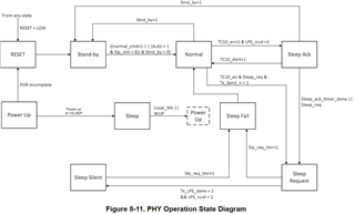
    8.4.5 Sleep Ack
    When the PHY receives low power sleep requests from the link partner, it enter Sleep Ack mode. In this mode,
    the PHY allows 8ms for the MAC to decide if TC-10 sleep mode must be enabled or not. If the MAC decides to
    allow TC-10, the PHY proceeds to the next step in TC-10 state machine.

    It seems the PHY2 shall resend a sleep request to complete the state transition. Which one is correct ?

    One more question, is the dp83tc812 driver is ready? dp83tc812.c The driver does not provide any interrupt handler.

    Thanks

  • Hi Mike,

    The working dp83tc812.c driver is available at the link you provided, it just does not have an interrupt handler feature.

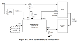
    This is the typical TC10 diagram from the datasheet:

    In PHY2, the the wake pin should already be pulled down by a 10k resistor.

    During power up, the SoC can assert the Wake pin HIGH to wake up the device. However, it should be normally pulled low to prevent wakeup during transition to sleep.

    Best regards,

    Melissa

  • Hi Melissa,

    The steps to test local sleep.

    1. Set PHY1 and PHY2 WAKE pin to high first and then low.
    2. Write 0x0002 to reg<0x018C>

    The INH pins of PHY1 and PHY2 are still high. The register of LPG_STATUS is 0x018e : 0x0004. It is still in NORMAL mode.

    Thanks

  • Hi Mike,

    • Does INH have a pull down like in the diagram above? If it is floating, INH will be Hi-Z. Can you provide a picture of your PHY schematic? 
    • Does the PHY show link up in register 0x1 before you write 0x18C=0x0002?
    • 0x18C is an extended register, are you writing to it with the correct extended register steps mentioned in the datasheet, section 8.6.1 Register Access Summary?

    Best regards,

    Melissa