Other Parts Discussed in Thread: TCAN4550
Tool/software:
1. What do i want to do?
I want to configure the Transimission Complete Interrupt to nINT pin, and when data is sent out, I can get the TC Interrupt notification from nINT's IRQ_Handler.
2. What is My Question?
1) I use following code (disable WDT, enable TC & RF0N irq) to initize the tcan4550-q1, and configures IRQ linked to nINT pin
2) Then using SPI to send data out.
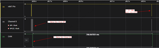
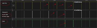
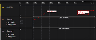
3) When SPI calling is over, it takes about 760ms + for the nINT pin to become low from high (which indicates the Transimmision Complete Interrupt happening)
My Question :
the TC interrupt waits too long to happen after sending data out, it should not be 760ms +, what is the root cause ? please help me to check the configurations. thank you so much ...
following figure shows the big delay
a) following is init code
/********************************************************************
function: board_canfd_ch1_cfg_init
discript:
entrance: none.
return  : none
********************************************************************/
void board_tcan4550_cfg(uint8_t baud_nom, uint8_t baud_dat)
{
    TCAN4x5x_Device_ClearSPIERR();                              // Clear any SPI ERR flags that might be set as a result of our pin mux changing during MCU startup

    /* Step one attempt to clear all interrupts */
    // TCAN4x5x_Device_Interrupt_Enable dev_ie = {0};              // Initialize to 0 to all bits are set to 0.
    // TCAN4x5x_Device_ConfigureInterruptEnable(&dev_ie);          // Disable all non-MCAN related interrupts for simplicity

    TCAN4x5x_Device_Interrupts dev_ir = {0};                    // Setup a new MCAN IR object for easy interrupt checking
    TCAN4x5x_Device_ReadInterrupts(&dev_ir);                    // Request that the struct be updated with current DEVICE (not MCAN) interrupt values

    if (dev_ir.PWRON)                                           // If the Power On interrupt flag is set
    {
        TCAN4x5x_Device_ClearInterrupts(&dev_ir);               // Clear it because if it's not cleared within ~4 minutes, it goes to sleep
    }

    /* Configure the CAN bus speeds */
    TCAN4x5x_MCAN_Nominal_Timing_Simple TCANNomTiming = {0};
    TCANNomTiming.NominalBitRatePrescaler    = baud_list[baud_nom][0];
    TCANNomTiming.NominalTqBeforeSamplePoint = baud_list[baud_nom][1];
    TCANNomTiming.NominalTqAfterSamplePoint  = baud_list[baud_nom][2];

    TCAN4x5x_MCAN_Data_Timing_Simple TCANDataTiming = {0};
    TCANDataTiming.DataBitRatePrescaler      = baud_list[baud_dat][0];
    TCANDataTiming.DataTqBeforeSamplePoint   = baud_list[baud_dat][1];
    TCANDataTiming.DataTqAfterSamplePoint    = baud_list[baud_dat][2];

    /* Configure the MCAN core settings */
    TCAN4x5x_MCAN_CCCR_Config cccrConfig = {0};                 // Remember to initialize to 0, or you'll get random garbage!
    cccrConfig.FDOE = 1;                                        // CAN FD mode enable
    cccrConfig.BRSE = 1;                                        // CAN FD Bit rate switch enable
    cccrConfig.DAR  = 0;                                        // Disable automatic retransmission

    /* Configure the default CAN packet filtering settings */
    TCAN4x5x_MCAN_Global_Filter_Configuration gfc = {0};
    gfc.RRFE = 1;                                               // Reject remote frames (TCAN4x5x doesn't support this)
    gfc.RRFS = 1;                                               // Reject remote frames (TCAN4x5x doesn't support this)
    gfc.ANFE = TCAN4x5x_GFC_REJECT;                             // Default behavior if incoming message doesn't match a filter is to accept into RXFIO0 for extended ID messages (29 bit IDs)
    gfc.ANFS = TCAN4x5x_GFC_REJECT;                             // Default behavior if incoming message doesn't match a filter is to accept into RXFIO0 for standard ID messages (11 bit IDs)

    /* ************************************************************************
     * In the next configuration block, we will set the MCAN core up to have:
     *   - 1 SID filter element
     *   - 1 XID Filter element
     *   - 5 RX FIFO 0 elements
     *   - RX FIFO 0 supports data payloads up to 64 bytes
     *   - RX FIFO 1 and RX Buffer will not have any elements, but we still set their data payload sizes, even though it's not required
     *   - No TX Event FIFOs
     *   - 2 Transmit buffers supporting up to 64 bytes of data payload
     */
    TCAN4x5x_MRAM_Config MRAMConfiguration = {0};
    MRAMConfiguration.SIDNumElements = 8;                        // Standard ID number of elements, you MUST have a filter written to MRAM for each element defined
    MRAMConfiguration.XIDNumElements = 1;                        // Extended ID number of elements, you MUST have a filter written to MRAM for each element defined
    MRAMConfiguration.Rx0NumElements = 5;                        // RX0 Number of elements
    MRAMConfiguration.Rx0ElementSize = MRAM_32_Byte_Data;        // RX0 data payload size
    MRAMConfiguration.Rx1NumElements = 0;                        // RX1 number of elements
    MRAMConfiguration.Rx1ElementSize = MRAM_32_Byte_Data;        // RX1 data payload size
    MRAMConfiguration.RxBufNumElements = 0;                      // RX buffer number of elements
    MRAMConfiguration.RxBufElementSize = MRAM_32_Byte_Data;      // RX buffer data payload size
    MRAMConfiguration.TxEventFIFONumElements = 5;                // TX Event FIFO number of elements
    MRAMConfiguration.TxBufferNumElements = 5;                   // TX buffer number of elements
    MRAMConfiguration.TxBufferElementSize = MRAM_32_Byte_Data;   // TX buffer data payload size

    /* Configure the MCAN core with the settings above, the changes in this block are write protected registers,      *
     * so it makes the most sense to do them all at once, so we only unlock and lock once                             */

    TCAN4x5x_MCAN_EnableProtectedRegisters();                    // Start by making protected registers accessible
    TCAN4x5x_MCAN_ConfigureCCCRRegister(&cccrConfig);            // Enable FD mode and Bit rate switching
    TCAN4x5x_MCAN_ConfigureGlobalFilter(&gfc);                   // Configure the global filter configuration (Default CAN message behavior)
    TCAN4x5x_MCAN_ConfigureNominalTiming_Simple(&TCANNomTiming); // Setup nominal/arbitration bit timing
    TCAN4x5x_MCAN_ConfigureDataTiming_Simple(&TCANDataTiming);   // Setup CAN FD timing
    TCAN4x5x_MRAM_Clear();                                       // Clear all of MRAM (Writes 0's to all of it)
    TCAN4x5x_MRAM_Configure(&MRAMConfiguration);                 // Set up the applicable registers related to MRAM configuration
    TCAN4x5x_MCAN_DisableProtectedRegisters();                   // Disable protected write and take device out of INIT mode

    /* Set the interrupts we want to enable for MCAN */
    TCAN4x5x_MCAN_Interrupt_Enable mcan_ie = {0};                // Remember to initialize to 0, or you'll get random garbage!
    mcan_ie.RF0NE = 1;                                           // RX FIFO 0 new message interrupt enable

    TCAN4x5x_MCAN_ConfigureInterruptEnable(&mcan_ie);            // Enable the appropriate registers

    /* Setup filters, this filter will mark any message with ID 0x055 as a priority message */
    TCAN4x5x_MCAN_SID_Filter SID_ID = {0};
    SID_ID.SFT   = TCAN4x5x_SID_SFT_RANGE;                    // SFT: Standard filter type. Configured as a classic filter
    SID_ID.SFEC  = TCAN4x5x_SID_SFEC_PRIORITYSTORERX0;           // Standard filter element configuration, store it in RX fifo 0 as a priority message
    SID_ID.SFID1 = 0x00;                                         // SFID1 (Classic mode Filter)
    SID_ID.SFID2 = 0x1F;                                         // SFID2 (Classic mode Mask)
    TCAN4x5x_MCAN_WriteSIDFilter(0, &SID_ID);                    // Write to the MRAM


    /* Configure the TCAN4550 Non-CAN-related functions */
    TCAN4x5x_DEV_CONFIG devConfig = {0};                        // Remember to initialize to 0, or you'll get random garbage!
    devConfig.SWE_DIS = 0;                                      // Keep Sleep Wake Error Enabled (it's a disable bit, not an enable)
    devConfig.DEVICE_RESET = 0;                                 // Not requesting a software reset
    devConfig.WD_EN = 0;                                        // Watchdog disabled
    devConfig.nWKRQ_CONFIG = 0;                                 // Mirror INH function (default)
    devConfig.INH_DIS = 0;                                      // INH enabled (default)
    devConfig.GPIO1_GPO_CONFIG = TCAN4x5x_DEV_CONFIG_GPO1_MCAN_INT1;    // MCAN nINT 1 (default)
    devConfig.FAIL_SAFE_EN = 0;                                 // Failsafe disabled (default)
    devConfig.GPIO1_CONFIG = TCAN4x5x_DEV_CONFIG_GPIO1_CONFIG_GPO;      // GPIO set as GPO (Default)
    devConfig.WD_ACTION = TCAN4x5x_DEV_CONFIG_WDT_ACTION_nINT;  // Watchdog set an interrupt (default)
    devConfig.WD_BIT_RESET = 0;                                 // Don't reset the watchdog
    devConfig.nWKRQ_VOLTAGE = 0;                                // Set nWKRQ to internal voltage rail (default)
    devConfig.GPO2_CONFIG = TCAN4x5x_DEV_CONFIG_GPO2_NO_ACTION; // GPO2 has no behavior (default)
    devConfig.CLK_REF = 1;                                      // Input crystal is a 40 MHz crystal (default)
    devConfig.WAKE_CONFIG = TCAN4x5x_DEV_CONFIG_WAKE_DISABLED;  // Wake pin can be triggered by either edge (default)
    TCAN4x5x_Device_Configure(&devConfig);                      // Configure the device with the above configuration

    TCAN4x5x_Device_SetMode(TCAN4x5x_DEVICE_MODE_NORMAL);       // Set to normal mode, since configuration is done. This line turns on the transceiver

    TCAN4x5x_MCAN_ClearInterruptsAll();                         // Resets all MCAN interrupts (does NOT include any SPIERR interrupts)
	//TCAN4x5x_Device_ClearSPIERR();
}


// Use this API to init TCAN4550
void board_tcan4550_init(uint8_t baud_nom,uint8_t baud_dat)
{
    tcan4550_spi_init(4);   // init SPI module

    uint16_t ver = TCAN4x5x_Device_ReadDeviceVersion();
    uint32_t id0 = TCAN4x5x_Device_ReadDeviceID0();
    uint32_t id1 = TCAN4x5x_Device_ReadDeviceID1();
    APP_LOG_INFO("CAN ID: 0x%08x.%08x, ver: 0x%04x", id0, id1, ver);

    board_tcan4550_cfg(BAUD_1000K, BAUD_4000K);

    /* enable all tx buffer interrupt */
    AHB_WRITE_32(REG_MCAN_TXBTIE, 0xffffffff);

	AHB_WRITE_32(0x800, 0x8004CA0);

    /* Enable irq */
    AHB_WRITE_32(0x10E0, 0x1);
	AHB_WRITE_32(0x1050, 0x0);
    AHB_WRITE_32(0x1054, 0x201);
    AHB_WRITE_32(0x1058, 0x201);
    AHB_WRITE_32(0x105C, 0x201);
    AHB_WRITE_32(0x0820, 0xFFFFFFFF);

	TCAN4x5x_Device_ClearSPIERR();
}
b) using following code to transmit data out
bool gwcp_spi2can_port_transmit(uint32_t can_id, uint8_t *p_data, uint8_t length)
{
	int buf_idx = 0;
	int ret = 0;
	TCAN4x5x_MCAN_TX_Header header = {0};

    header.DLC = len2dlc(length);
    header.ID  = can_id;
    header.XTD = 0;
    header.BRS = 1;
    header.FDF = 1;
	header.RTR = 0;

    ret = TCAN4x5x_MCAN_WriteTXBuffer(buf_idx, &header, p_data);

	TCAN4x5x_MCAN_TransmitBufferContents(buf_idx);

	return true;
}