This thread has been locked.

If you have a related question, please click the "Ask a related question" button in the top right corner. The newly created question will be automatically linked to this question.

TPD8S009: UCLAMP0502P.TCT

Part Number: TPD8S009
Other Parts Discussed in Thread: TPD6E05U06

Tool/software:

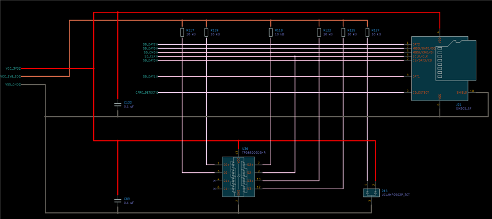
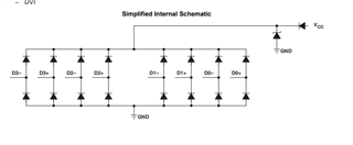
I am using the following eight-channel TVS ESD protection diode (TPD8S009DSMR)  connected to some signals of the MicroSD card as shown in the following diagram, and other TVS ESD protection diode (UCLAMP0502P.TCT) for the Card_Detect signal.

Since I have two unconected pins on the TPD8S009DSMR, my question is whether I can remove the UCLAMP0502P.TCT and connect the card_detect signal to one of the unconected pins on the TPD8S009DSMR.

  • Hi Juan,

    You can connect the input to the Vcc pin, but keep in mind the zener diode conencted at the Vcc pin to GND is also connected in parallel at each input to GND. 

    The Zener diode and input diodes would be clamping the transient in a configuration we have not characterized in the datasheet. I would recommend testing the clamping voltage in your system to make sure it's low enough for the downstream circuitry. 

    Regards,

    Sebastian

  • 1) According to the datasheet the forward diode voltage max is 0.95V and my SD signals work at 1.8V. Is there a problem with this?

    2) On the other hand, my Vcc is 3.3V. Is there a problem if I connect it to the Vcc of the TPD8S009?
    If there is a problem, could the Vcc of the TPD8S009 be left unconnected?

  • Juan,

    1. There will be no issue here, this is just the forward diode drop of an individual steering diode at an input. Each input won't breakdown until 9V. 

    2. There is no issue with using a 3.3V Vcc. 

    I would recommend a different device if you're going to leave the Vcc pin connected, this configuration will increase the breakdown voltage of each input resulting in higher clamping voltage. I would recommend TPD6E05U06. 

    Regards,

    Sebastian