Part Number: TUSB322I
Other Parts Discussed in Thread: TUSB322,
Tool/software:
Hi TIer
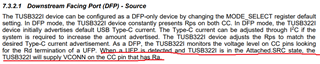
When we tested TUSB322IRWBR as DFP and external fast charging function, we found that when TUSB322 was set to 5/3A fast charging, the CC1 voltage was 1.67V using the POWER-Z tool to monitor, which met the 5V/3A judgment standard in the PD protocol, but the actual connection to the mobile phone could only reach 5V/0.5A; when TUSB322 was set to 5/1.5A fast charging, the CC1 voltage was 0.96V using the POWER-Z tool to monitor, which met the 5V/1.5A judgment standard in the PD protocol, but the actual connection to the mobile phone could only reach 5V/0.5A. When the mobile phone's built-in fast charging charger was used to power the mobile phone, it was measured to reach 9V/1.5A. It seems that there is a problem with the negotiation. Please help to divide the possible reasons, thank you!
Huawei phones/tablets, and Xiaomi phones are in the same situation. They should all be PD protocols, because these phones can negotiate successfully with PD protocol chargers, and PWOER-Z also shows that the protocol at this time is PD3.0.
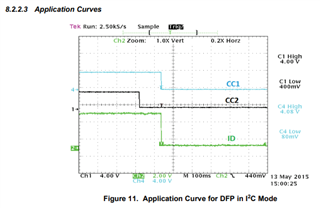
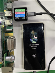
This is a picture of the negotiation between a Huawei phone and a charger. At this time, the voltage of CC1 is 1.67V (5V/3A judgment standard), and the voltage of CC2 is 0.33V:
When TUSB322 is set to 5/3A fast charge, POWER-Z tool is used to monitor that when the Type-C to Lightning is plugged in to power an Apple phone, it can reach 5V/1.5A. At this time, the voltage of CC1 is 1.91V (5V/3A judgment standard), and the voltage of CC2 is close to 0V.
According to the PD protocol standard, if the cable does not have an E-marker, the idle CC pin should be 5V or 3.3V. For example, this is the case when TUSB322 is connected to a mobile phone via the standard type-c. The above does not seem to comply, so why can it work normally?
Thank you very much.