This thread has been locked.

If you have a related question, please click the "Ask a related question" button in the top right corner. The newly created question will be automatically linked to this question.

DS125BR401: what will be the output signal when input signal is low-frequency square wave?

Part Number: DS125BR401

Tool/software:

dears,

When using DS125BR401 and configuring the mode to KR mode, and the input signal is a low-frequency square wave (for example, 50 Hz), will the output end synchronously receive a 50 Hz square wave? Please help to confirm, thank you.

  • Hi Andrew,

    Yes the output will be synchronous to the input. DS125BR401 transmits the same signal at its input to the output driver after applying equalization.

    Best,

    Lucas

  • dear Lucas,

    thanks a lot.

    the customer met eye diagram quality issue. they are asking for the guidance to improve the eye diagram quality? do we have any detailed guidance document?
    The customer found that adjusting the DEM register may be of help to improve the eye diagram quality, but adjusting the VOC register did not help at all.

    thank you!

  • Hi Andrew,

    Some manual tuning is required to optimize DS125BR401 equalization. Allow me to explain each of the tunable parameters.

    • CTLE (continuous time linear equalizer): This is the primary RX equalization block. Boost is applied at the redriver receiver to compensate for insertion loss on the RX channel. Boost levels are given in Table 2 in the datasheet. I recommend tuning this parameter first.
      • If you have a measure/estimate of the insertion loss on the RX channel, you can start with an EQ level with matching boost. Step the EQ level up/down until the best eye diagram is observed.
      • If you do not have a measure/estimate of insertion loss, start with minimum EQ setting. Step the EQ level up until the best eye diagram is observed.
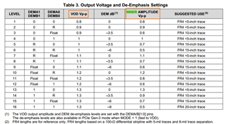
    • DEM (de-emphasis): This is the primary TX equalization block. The signal is attenuated as a form of pre-distortion to improve eye opening at a downstream receiver. De-emphasis levels are given in Table 3 in the datasheet. I recommend tuning this parameter after CTLE. High de-emphasis settings may impact auto-negotiation and link training pass through performance, if you are using these protocols.
      • Start with DEM=0 setting. Step the DEM level up until the best eye diagram is observed.
    • VOD (differential output voltage): This is the primary output amplitude control. In 10G-KR mode, the redriver maintains signal chain linearity. This means the output amplitude will track the input amplitude and the VOD values shown in Table 3 are not maintained for all input amplitude levels. I recommend tuning this parameter last, and using a setting of 1V or higher if you are using auto-negotiation and link training protocols.
      • VOD setting will likely have minimal impact on eye opening.

    Note that 10G-KR mode maintains a linear signal path to pass through auto-negotiation and link training protocols. Lower de-emphasis setting and higher VOD setting preserve better signal chain linearity.

    Best,

    Lucas

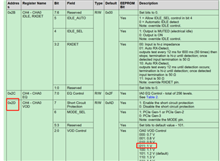
  • hello  1. Debug VOD according to the register in the picture and observe the TX amplitude in the eye diagram. No significant changes were found. May I ask if I want to debug VOD directly by debugging this register in the picture
    What is the difference between VOD Vp-p and INNER Vp-p for the two selected parameters in the following picture

  • Hi Evan,

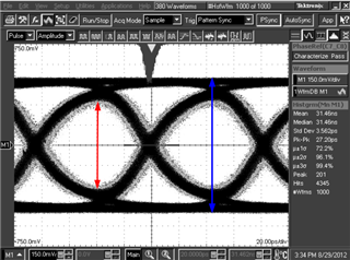
    The red arrow shows inner amplitude, also known as eye height. The blue arrow shows VOD or outer amplitude. As you can see in Table 3, higher de-emphasis setting results in smaller inner amplitude.

    Note that you will not observe these exact VOD and inner amplitude values when the device is configured in 10G-KR mode. 10G-KR mode changes the signal chain to maintain linearity, meaning the output ampitude will track the input amplitude more closely.

    Best,

    Lucas

  • 1 At present, the operation mode of adjusting register configuration VOD is correct, can you understand it this way?

    2 The reason why we adjusted the VOD and did not see a significant change in amplitude is because our mode configuration is KR mode. Can we understand it normally;

    3 Is it impossible to improve eye diagram by adjusting amplitude in KR mode

  • Hi Evan,

    1. If you are writing register 0x2D bits 2:0 to modify the VOD setting on channel A0 only, then your register configuration is correct.

    2. Yes that's correct, changing VOD setting is not expected to cause a significant change in 10G-KR mode.

    3. In any operational mode, VOD setting is not expected to have much impact on eye opening. This is because VOD controls the outer amplitude. CTLE is the primary setting to improve eye opening, and DEM can assist as well. Please refer to my explanations of these settings above.

    Best,

    Lucas

  • Do I want to debug TX by debugging CTLE registers

  • Hi Evan,

    CTLE compensates for insertion loss and signal integrity on the RX side of the device, however this will improve how the eye diagram looks on the TX side. The majority of equalization performed by a redriver happens on the RX side.

    Your downstream receiver on the TX side of the redriver likely has some EQ capability which can compensate for loss on this channel. The DEM setting on the redriver can help improve signal quality on the TX side by pre-distorting the signal, however high de-emphasis setting can impact the performance of 10G-KR protocols such as auto-negotiation and link training.

    Best,

    Lucas