This thread has been locked.

If you have a related question, please click the "Ask a related question" button in the top right corner. The newly created question will be automatically linked to this question.

TLK10002 IBIS Model Problem

Other Parts Discussed in Thread: TLK10002

Hello,

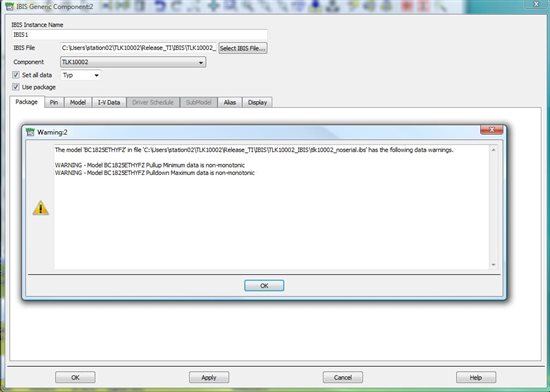
I am trying to run the IBIS model with ADS. Below is the warning received. May i know how to resolved this problem?
TLK10002_IBIS_Model.jpg
TLK10002_IBIS2.jpg
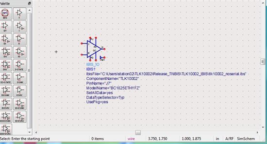
Lastly, the model imported is depicted as picture below. How to correspond the IBIS Model I/O pin with the TLK10002 chip's pin. What does the symbol T,E, PU etc means?
TLK10002_IBIS3.jpg
Thank you
Regards
Jaz

  • Hi Jaz,

    The images in your post are not showing up.  It looks like you may have tried hotlinking them from a Gmail account.  Could you please try hosting them somewhere else or uploading them to the E2E site?  You can use the "insert image" feature in the toolbar at the top of the text input field.  The same applies to your other recent post as well.

    Thank you,
    Max Robertson
    Analog Applications Engineer
    Texas Instruments
    m-robertson@ti.com

  • Hello Max,


    Attached is the error when i am trying to use the IBIS model in ADS software. 


    The pins ADS can read from the IBIS model is shown below. Assuming this is all the I?O pin the model have, do you know what the pins description?


    Thank you in advance for your advice,


    Regards

    Jaz

  • Jaz,

    Those warnings are valid.  The model data will not match an idealized case since it was derived from real lab data.  The actual device must have shown some non-zero clamp current, non-monotonic pull-ups, etc.  These should be warnings rather than errors, and should not prevent the simulation from working.

    The model itself should contain all the input and output pins except for the serial I/O (IN/OUT and HSTX/HSRX).  There might be some problem with the import - are you bringing in the entire device model or just a single IO?  There will be several IOs contained within the device model.

    Best regards,
    Max Robertson

  • Hello Max,


    In ADS, each IBIS model requires to import a specific IBIS model file. So the entire IBIS model with typical, min. and max., will be selected. ADS user may choose min , max or typical for corner simulation. I can only select to import the entire ibis file provided. It does not have option to select just single I/O. Please consult me on how to import and use the model. If the model can only work with single I/O, can you please provide me the ibis file with single I/O only?

    Thank you


    Regards

    Jaz

  • Jaz,

    The file that we provide describes almost all of the device's I/O pins (it excludes the serial I/O).  Each one is assigned an IBIS model.  There are eight different models used:

    • BC1825ETHYFZ
    • IC18THY
    • IC18THYPDFZ
    • IC18THYPUFZ
    • ICLKRX18G
    • OC1840DTFZ
    • OC1850BTFZ
    • OCML11G

    If you open the model in a text editor (such as WordPad; NotePad will not display it properly), you can see a list of all the pin numbers, their names, and then the models associated with each one.  Each of these models is then defined later on in the file in terms of typ/min/max parameters.

    I am not familiar with ADS, but if there is a limitation with using only one model, you should be able to extract the model you want from the .ibs file we provide.  Just choose which model you want (based on the pin you are interested in), then find the model description underneath the [Model] heading in the .ibs file.  You can move the model you want to a different file, or delete the models you don't want from the existing file.

    Please let me know if you have any problems using this approach.

    Best regards,
    Max Robertson