This thread has been locked.

If you have a related question, please click the "Ask a related question" button in the top right corner. The newly created question will be automatically linked to this question.

TMUXHS4412: TMUXHS4412RUAR how to design with the unused channel

Part Number: TMUXHS4412

Tool/software:

Hi   TI,

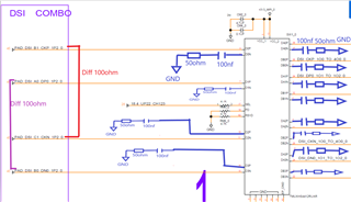
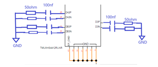
      we'd like to select TMUXHS4412RUAR on MIPI verification.

      I have two questions:

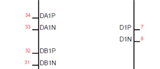
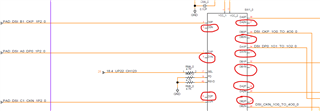
     1) to get a better crosstalk, we'd like to make the gap bigger between used pads. For the unused ports P or N, how should we design? 

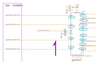
       2) for the below unused channels P and N, how should we design? 

  • Hi Aimee,

    For any unused channels or ports, we recommend pulling these pins down to ground with a 100nF capacitor and a 50ohm termination resistor.

    Please let me know if you have any other questions.

    Thanks,

    Ryan

  • Hi   Ryan,

          situation A:  we just select D0P, and do not select D0N. For these unused channels, designed as below, correct?

          situation B: we do not select D3P and D3N.For these unused channels, designed as below, correct?

  • Hi   Ryan,

          because we have already completed the placement on the board and there is not enough space to place these 100nf capacitors and 49.9R resistance. I'd like to check with you:

           1)  If we do not add these capacitors and resistors on the unused channels and ports, what's the risk?

           2) can we place these capacitors and resistors far away from the switch?

  • Hi Aimee,

    1)  If we do not add these capacitors and resistors on the unused channels and ports, what's the risk?

    These can be left floating if needed. The capacitor and termination to ground is more of a precaution than a requirement, it is not needed. I am not sure as to what the risk would be if any without it.

    One thing I would like to bring up, you mentioned you're doing MIPI signaling. From my understanding, MIPI is differential signaling. Additionally, it looks like you have positive and negative data and clock signals acting as single-ended signals. Why can't these both be put through one channel as differential signals? Are these different sources? In my head, it looks like these can be routed as differential and not single ended.

    Thanks,

    Ryan

  • Hi Ryan,

         1) we could pull these unused channels down to ground with a capacitor and resistor as you recommended. May I place these components far away from the switch? 
           2) yes, MIPI is differential signaling, you could refer to my above Circuit which highlight the differential pairs. We plan to select D0P and D2N as one CLK differential pair and select D1P and D3N as one data differential pair. Why I have this kind of design is for a better crosstalk. We found the crosstalk result can not meet the simulation spec if we put through one channel as differential signals.


  • Hi Aimee,

         1) we could pull these unused channels down to ground with a capacitor and resistor as you recommended. May I place these components far away from the switch? 

    If you wish to do this you can, however, I believe leaving it floating is fine as well.

    2) yes, MIPI is differential signaling, you could refer to my above Circuit which highlight the differential pairs. We plan to select D0P and D2N as one CLK differential pair and select D1P and D3N as one data differential pair. Why I have this kind of design is for a better crosstalk. We found the crosstalk result can not meet the simulation spec if we put through one channel as differential signals.

    We recommend against this. For starters, differential signaling should already be working to reduce or eliminate crosstalk all together. If you are seeing crosstalk issues, I am not sure if they are coming from this mux, or from somewhere else in your system. Additionally, by routing these signals as you have them now, you are already breaking differential characteristics. This can make the signal more susceptible to noise or reflections in the signal, resulting in degraded signal quality. We don't see any reason why this mux would cause crosstalk issues, as long as it is routed differentially.

    As for the other parts of the schematic, the only recommendation I have would be is to have the caps at VCC more similar to what is in the EVM: 

    Please let me know about any other questions.

    Thanks,

    Ryan

  • Hi   Ryan,

          1) The crosstalk issue existed between DSI COMBO to CSI COMBO CPHY0. Previous solution is to select D1P for PAD_DSI_A0_DP0_1P2_0 and D1N for PAD_DSI_B0_DN0_1P2_0, DB1P for PAD_CSI_A0_DP0_1P2_0 and DB1N for PAD_CSI_B0_DN0_1P2_0. However, due to the pad gap is too close, even if we made the trace gap as wide as we can, the crosstalk is -15dB. Then, we updated the solution to separate the DSICOMBO with different ports, that is D1P for PAD_DSI_A0_DP0_1P2_0, D3N for PAD_DSI_B0_DN0_1P2_0, DB1P for PAD_CSI_A0_DP0_1P2_0, DB3N for PAD_CSI_B0_DN0_1P2_0, then the crosstalk reduced to -24dB. 

            2) Based on the above explanation, I'd like to check with you if it's fine to leave the unused channels floating as our existing circuit? like the below channels marked with red circle.

  • Hi Aimee,

    1) The crosstalk issue existed between DSI COMBO to CSI COMBO CPHY0. Previous solution is to select D1P for PAD_DSI_A0_DP0_1P2_0 and D1N for PAD_DSI_B0_DN0_1P2_0, DB1P for PAD_CSI_A0_DP0_1P2_0 and DB1N for PAD_CSI_B0_DN0_1P2_0. However, due to the pad gap is too close, even if we made the trace gap as wide as we can, the crosstalk is -15dB. Then, we updated the solution to separate the DSICOMBO with different ports, that is D1P for PAD_DSI_A0_DP0_1P2_0, D3N for PAD_DSI_B0_DN0_1P2_0, DB1P for PAD_CSI_A0_DP0_1P2_0, DB3N for PAD_CSI_B0_DN0_1P2_0, then the crosstalk reduced to -24dB. 

    This is very odd behavior, the mux really shouldn't be causing the crosstalk to be this bad. Again, I would recommend against routing these differential signals as single ended, even if only for the area around the mux. If you do decide to go ahead and use it as such, we can't guarantee that there will not be any adverse effects to the signal.

          2) Based on the above explanation, I'd like to check with you if it's fine to leave the unused channels floating as our existing circuit? like the below channels marked with red circle.

    Yes, it is okay to leave those channels floating, there should be no issue from that.

    Thanks,

    Ryan