This thread has been locked.
If you have a related question, please click the "Ask a related question" button in the top right corner. The newly created question will be automatically linked to this question.
Tool/software:
Hello,
We are using DP83822HFRHBR with STM32H7 MUC in RMII mode, and we are not able to Detect the PHY using PHY ADDRESS.
We checked below for Verification,
1. 25MHz Clock input to PHY --> coming good.
2. Power Supply to PHY is fine.
3. Soldering of QFN is Fine.
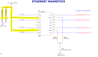
Please find the attachment for Schematic for the Same to guide how to proceed.
Hi Rajeshnag,
Thank you for submitting your query and for providing the schematic. From the schematic I can see that the expected PHY Address is '1'.
Is register access what is not currently working? If the ethernet cable is connect, does the PHY link up?
Regards,
Alvaro
Hello Alvaro,
We have not connected Ethernet Cable,
It is the first time we are using with STM, and as initial step we just tried to Detect the PHY using MDC,MDIO.
How can we read register of PHY? since we did not see PHY detected.
Kindly help in details, i will loop this information to my software team for more details.
Thanks in Advance.
Thanks
Rajesh
Hi Rajesh,
What OS are you using and how are you attempting to detect the PHY using MDC/MDIO?
If running Linux, please see this FAQ.
Also on Linux, can you run the command: dmesg | grep mdio
Regards,
Alvaro
Hi Alvaro,
We have connected STM32H7 RMII Lines to DP83822, we have tried the below,
We read the PHYIDR 1 and PHYIDR2 Registers, and we verified with Datasheet Values 0x2000 and 0xA240.
I need help in confirming this, whether PHY is detected correctly or Not? also PHYIDR1 & PHYIDR2 is the exact register we need to check
Regards
Rajesh
Hi Rajesh,
Are you saying that you were able to successfully read registers 0x2 & 0x3? If so then yes, the PHY is detected! Register access is a good indication if the PHY is alive and if the correct PHY Address is configured.
Regards,
Alvaro
Hello Alvaro,
In continuation to Testing, We started Testing RMII, But not able to establish the Connection.
Can you Pls suggest which register to read to debug the issue?
Also we are using RMII Interface, the Strapping for RX_DV need to be changed? to MODE2 i,e RMII_EN =1 and XI=0 we are using 25MHz clock input for the PHY.
Thanks in Advance
Regards
Rajesh
Hi Rajesh,
Can you confirm if there is link up (read Register 0x1[2]) when the ethernet cable is connected? This is to confirm that the MDI portion of the PHY is good.
Reg 0x17 can be used to confirm the RMII settings. Bit 9 and 7 should both be '0' and Bit 5 should be '1'. RX_DV should be in Mode 3 (5.76k PU and 2.49k PD).
Extended Registers 0x467 & 0x468 can be used to confirm the strap settings. Please see this FAQ for how to access them.
Regards,
Alvaro
Hello Alvaro,
Thanks for the details and procedure.
In this case,
RX_DV should be in mode 3 in Hardware Settings i, e R226 & R240 is fitted with recommended Resistor? or can it be set using Software?
Currently I have followed EVK reference and RX_DV is in default mode i, e OPEN OPEN. (No Resistor Value placed on RX_DV line)
You can once check attached schematic in first thread.
Waiting for your feedback.
Thanks in advance.
Regards
Rajesh
Hello Alvaro,
I have made the RX_DV changes with resistors and below are the registers we read from PHY.
Register Name | Register Address | Description | Value Read |
DP83822_BCR | 0x0000U | //Basic Mode Control Register | 0x3100 |
DP83822_BSR | 0x0001U | //Basic Mode Status Register | 0x7849 |
DP83822_PHYI1R | 0x0002U | //PHY Identifier Register #1 | 0x2000 |
DP83822_PHYI2R | 0x0003U | //PHY Identifier Register #2 | 0xA240 |
DP83822_ANAR | 0x0004U | //Auto-Negotiation Advertisement Register | 0x01E1 |
DP83822_ANLPAR | 0x0005U | //Auto-Negotiation Link Partner Ability Register | 0x0000 |
DP83822_ANER | 0x0006U | //Auto-Negotiation Expansion Register | 0x0004 |
DP83822_ANNPTR | 0x0007U | //Auto-Negotiation Next Page Register | 0x2001 |
DP83822_ANLNPTR | 0x0008U | //Auto-Negotiation Link Partner Ability Next Pag | 0x0000 |
DP83822_CR1 | 0x0009U | //Control Register #1 | 0x0000 |
DP83822_CR2 | 0x000AU | //Control Register #2 | 0x0100 |
DP83822_CR3 | 0x000BU | //Control Register #3 | 0x1000 |
DP83822_REGCR | 0x000DU | //Register Control Register | 0x0000 |
DP83822_ADDAR | 0x000EU | //Data Register | 0x0000 |
DP83822_FLDS | 0x000FU | // Fast Link Down Status Register | 0x0000 |
DP83822_PHYSTS | 0x0010U | //PHY Status Register | 0x4002 |
DP83822_PHYSCR | 0x0011U | //PHY Specific Control Register | 0x0108 |
DP83822_RCSR | 0x0017U | //RMII and Status Register | 0x0061 |
DP83822_PHYCR | 0x0019U | // PHY Control Register | 0x8021 |
DP83822_PHYRCR | 0x001FU | // PHY Reset Control Register | 0x0000 |
Please check and let me know to proceed further.
Regards
Rajesh
Hi Rajesh!
Thank you for clearly providing the register log in a table, this makes it much easier for me to review. Please find my responses below.
RX_DV should be in mode 3 in Hardware Settings i, e R226 & R240 is fitted with recommended Resistor? or can it be set using Software?
That is correct! Populate R226 & R240 with the recommended 5.76k PU and 2.49k PD resistors to configure the DP83822 in the correct RMII mode. I had mentioned Reg 0x17 to confirm the RMII settings, but didn't directly mention that Reg 0x17 can be used to set the RMII setting as well.
From the Register log I see that Reg 0x17 = 0x0061, which is good! RMII is enabled (bit 5) and set to operate off a 25 MHz input clock (bit 7).
Reg 0x1 = 0x7849, which means there is no link. When these register reads were performed, was the ethernet cable connected to a link partner?
Reg 0x5 = 0x0000 implies that the cable was not connected.
Are you still experiencing communication issues?
Currently I have followed EVK reference and RX_DV is in default mode i, e OPEN OPEN. (No Resistor Value placed on RX_DV line)
The EVM is strapped for MII mode, strap settings will depend on the desired mode.
Regards,
Alvaro
Hello Alvaro,
Thanks for the Review, Yes we are still not able to establish the communication.
Yes, We were connected Ethernet cable while reading the Register.
For your information we are trying with windows system, is there any special modification or driver required for the same?
Is there any point I can physically probe some signals to verify the PHY.
Thanks in advance.
Regards
Rajesh
Hi Rajesh,
This is strange, the PHY should have been able to link up when the ethernet cable is connected. Looking at the MDI portion of your schematic, the only thing I can see that might be off is described in the table below. When the Ethernet cable was connected, what was the Link Partner? Can we confirm if the Link Partner is able to link up with other ethernet devices?
Customer Schematic | Datasheet Recommendation | Remark |
![]() |
![]() |
Center taps should both have their own 0.1 & 1 uF caps. Customer's schematic shows both center taps connected to the same caps. I doubt this is the cause for the current issue, but is worth pointing out. |
We do not have a windows driver, we only have drivers for RTOS and Linux, which can be found on our Ethernet Software Page.
Regards,
Alvaro
Hello Alvaro,
Thank you very much for your detailed review and support.
I’m pleased to inform you that we have successfully established the connection with the PC.
When our board is connected to the Windows PC, it detects the Ethernet connection, and the speed tab correctly identifies 100 Mbps (even without internet access).
The issue was traced back to the baseboard connection, as we are using a stacked board design.
Our software team is now working further on this.
Thanks for the support again.
Best Regards
Rajesh
Hi Rajesh,
Glad to hear that everything seems to be working now! I will close this thread. If another issue arise, feel free to start a new E2E post!
Regards,
Alvaro