Tool/software:
Hi
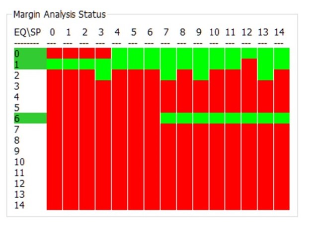
Can you review my customer's Margin Analysis result as below, is this result look ok ? (customer's cable is 4 meter)

This thread has been locked.
If you have a related question, please click the "Ask a related question" button in the top right corner. The newly created question will be automatically linked to this question.
Tool/software:
Hi
Can you review my customer's Margin Analysis result as below, is this result look ok ? (customer's cable is 4 meter)

Hello,
Yes, the MAP result here would be considered passing.
In general, TI recommends having a margin of at least three EQ levels with four passing strobe positions, including a contiguous rectangle of passing states that measures two EQ levels by four strobe positions.
The rectangle here would be EQ levels 0 and 1, with the third EQ level being EQ 6.
The application note here documents more in depth Margin Analysis Program results: FPD-Link Margin Analysis Program (MAP) user's guide
Typically we would expect to see more margin when using the DS90UB934. Would you be able to share what the cable type being used is here?
Best,
Zoe
Hi Zoe,
Thanks for the reply, the cable we are using is a 4m RG58 coax cable connect to DS90UB934..
Because we have 8 camera ports on our system, each port has similar but different margin analysis result.
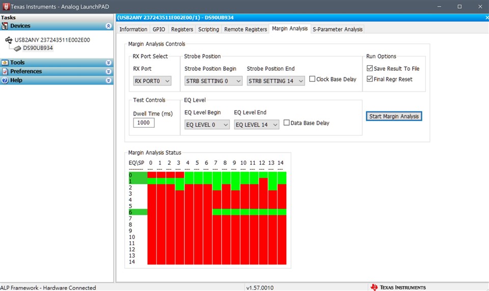
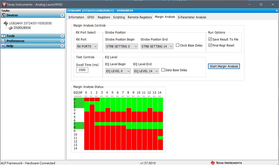
Even the same port, the result is a little different each time. Sometimes EQ6 can pass, and sometimes EQ5 can pass.
Please reference the test results below, I test the same port and the same cable 3 times and the results are different.
So it's hard to choose EQ5 or EQ6 as the third EQ level.
And we want to use the same EQ table for all 8 camera port.
Is there any way to increase the EQ range (possibly to EQ2), so that we can have solid EQ table?
BTW, we another question.
We have tried different length cable, it seems that the longer cable have better EQ range.
The shorter cable should have better signal quality, but why it's EQ range worse than the longer cable?
4m cable

8m cable

14m cable

Hi Joe,
Margin analysis program will not necessarily change based on the EQ settings placed on the deserializer. The MAP tool analyzes the link quality of the system (SER -> cable -> DES) by checking for forward channel errors at different EQ and strobe positions, so it allows you to see how different cables affect the link. To expand the green area, we would need to take a look at the hardware set-up.
I'd recommend checking if there is any damage to the 4m cable being used here. While the MAP tool is a good indicator of whether your system has enough margin, it is recommended that you measure the IL/RL parameters of the entire system to ensure that it passes the FPD-Link channel specifications. For instance, the 4m cable may have a higher insertion loss / return loss than expected here.
Best,
Zoe