This thread has been locked.

If you have a related question, please click the "Ask a related question" button in the top right corner. The newly created question will be automatically linked to this question.

TUSB501-Q1: TUSB501-Q1 SS polarity swap issue

Part Number: TUSB501-Q1
Other Parts Discussed in Thread: TUSB501

Tool/software:

HI BU team

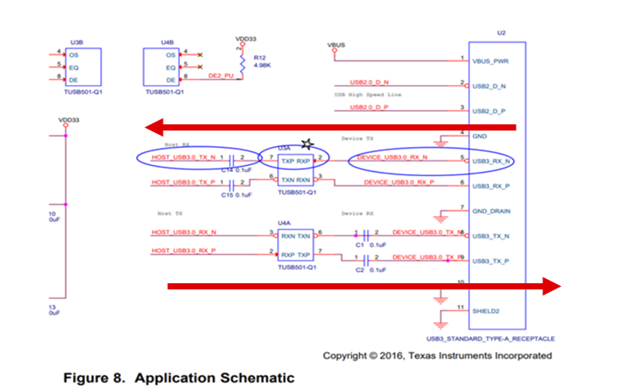
My customer followed the reference design shown in the datasheet Figure 8. Now customer reported that the SS channel with U3A could not communicate with the devices. And After double checked , U3A's pin as TXP/NXP are connected with the RXN/TXN of host and usb connector. Would you help double check if the reference design is right on U3A ? If it is wrong, what's the workaround under  no re-design PCB layout? and pls correct it in the datasheet ASAP.!

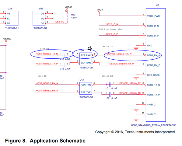
And I also found below description in 12 layout section. If implement this polarity swap function, what's the connections between host/ connector and tusb501?

Thanks 

  • Hi,

    The datasheet is correct. USB3 spec defines the USB Type-A receptacle RX (pin 5 and 6) to be receiver and TX (pin 8 and 9) to be transmitter, so the overall data flow is shown below.

    Please double check the USB Host TX and RX definition. If the USB Host TX is an output, then it needs to be connected to TUSB501 RX (input). If USB Host RX is an input, then it needs to be connected to TUSB501 TX (output). 

    USB3 spec supports polarity swap. So for TXP/N, you can swap its polarity between the P and N, same also applies to RXP/N.

    Thanks

    David