Because of the Thanksgiving holiday in the U.S., TI E2E™ design support forum responses may be delayed from November 25 through December 2. Thank you for your patience.

THVD8010: THVD8010 used on the THVD8000 EVM

Part Number: THVD8010
Other Parts Discussed in Thread: THVD8000

Tool/software:

Hi experts,

This is Skylar responsible for GREE as an FAE. 

May I ask if THVD8010 could bom-to-bom replace THVD8000 and be used in the THVD8000 EVM?

Also, may I ask if CAN transmit power as well? Why if CAN trasmits power, it will lose arbitration capability?

BR,

Skylar

  • Hi Skylar,

    The THVD8010 is pin to pin with THVD8000, and it should work fine in the THVD8000 EVM. Just note that Table 3-1 in the EVM guide will be different since THVD8010 has a smaller carrier frequency range.

    Please reference this E2E thread about CAN transmitting power: https://e2e.ti.com/support/interface-group/interface/f/interface-forum/1314001/power-over-data--can-bus

    Regards,

    Ethan

  • Hi Ethan,

    Thanks for your reply.

    Here are more questions from my side.

    1. If they want to isolate the signal of THVD8010, can they use opto-coupler? How many opto-coupler should they use for one THVD8010?

    2. Do they only need one DC supply to power supply all the load of all the buses? Should the DC supply only be on the main bus? What voltage value should the DC supply be? 

    3. Will the ripple of the DC supply influence the communication signal? Do we have the solution to avoid it?

    4. Should customer add any protection to prevent over-current, over-voltage or over-temp to the communication?

    5. Could you pls help make a comparison table between PB620 and THVD8010?

    6. If customer want to test THVD8000 EVM, they need to test two EVM which connect to each other right? And they could decide which one is the main bus by controlling the MCU, right?

    BR,

    Skylar

  • Hi Skylar,

    Our THVD80X0 design guide will likely help with most of these questions: https://www.ti.com/lit/pdf/slla496

    1. Opto-coupler are not suggested. The signal and power are already combined so separating these would not be helpful. If the customer is looking for additional protection through isolation, a transformer could be used in an AC situation. This application note has section on this: https://www.ti.com.cn/cn/lit/an/slla590/slla590.pdf?ts=1691425301940

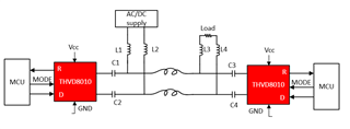
    2. Only one DC supply is necessary on the bus. Figure 8-1 in the design guide shows the correct setup. The second link I attached also discusses DC voltages. 

    3. The THVD80X0 series uses OOK modulation so typical DC ripple should not affect the signal output of the R pin. This would be filtered out by the transceiver. 

    4. Protection diodes can be placed on the bus for additional protection. 

    5. I am not seeing the PB620 device. However, most powerline devices are all very different from each other. This would means it would be very hard to compare them since there specs all vary

    6. Two EVMs can be used to test this, that is correct. The MODE pin is used to switch the devices from transmit to receiver mode. So both devices could be tested receiving and transmitting. 

    Regards,

    Ethan

  • Hi Ethan,

    Thanks for your detailed reply.

    If customer wants to use DC supply, they could not use transformers right? How could they to do the isolation when using DC power?

    BR,

    Skylar

  • Hi Skylar,

    In the DC configuration, the capacitors C1, C2, C3, and C4 act as the "isolation" barrier since they behave as an open circuit with DC. Otherwise, AC transformers are the only external method of adding isolation to this device. 

    Regards,

    Ethan