This thread has been locked.

If you have a related question, please click the "Ask a related question" button in the top right corner. The newly created question will be automatically linked to this question.

TUSB501: schematic check

Part Number: TUSB501
Other Parts Discussed in Thread: TUSB522P

Tool/software:

Hi 

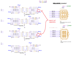
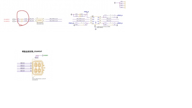
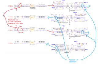
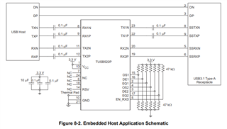
Could you help check the below TUSB501 schematic and any need to adjust

1. Please help confirm that usb3 is applicable, right?

2. The directivity of the component means that the signal tx is connected to the receiving end rx of the component, right?

3. DE\OS\EQ, what is the default pu\pd?

TUSB501 schematic.pdf

  • Hi Gareth,

    1. Not sure what you mean here. The connectors do not look like any of the standard USB-A, B, or C connectors. What application is the customer going for?

    2. The routing in your schematic looks correct with respect to the TUSB501Q1 devices. Each 501Q1 will pass the signal from the RX pins to the TX pins.

    For example if you want the USB host SSTX to connect to the TUSB501Q1 RX pins, then the TUSB501Q1 TX pins should connect to the SSTX on the USB connector. This would be the TX signal path.

    3. The pu/pd options you have in the schematic look ok. The actual best setting should be determined once your board is manufactured and validated. Having the option to solder/de-solder these resistors allows you to tune the settings appropriately.

    4. The 17V clamp voltage on your ESD diodes is too high for our device. I recommend using a diode with a clamp voltage around 3V to 4.3V.

    5. You need to AC couple the transmitters between the TUSB501Q1 and the USB connector with 0.1uF capacitors. Use 0201 as the footprint size for these.

    Best,

    Shane

  • Hi Shane

    1. Not sure what you mean here. The connectors do not look like any of the standard USB-A, B, or C connectors. What application is the customer going for? =>This connector is for electric vehicle applications.

    5. You need to AC couple the transmitters between the TUSB501Q1 and the USB connector with 0.1uF capacitors. Use 0201 as the footprint size for these.=> We have already placed a 0.1µF capacitor on the TUSB501 front end. Do we need to place one on the rear end as well?

  • Hi Gareth,

    You need to AC couple the TUSB501 transmitters with 0.1uF capacitors on both the front end and back end. Right now I only see 0.1uF capacitors on two of the TUSB501 receivers which is not correct. Receivers should use 0.33uF capacitors when connecting to a cable: 

    If the 0.1uF receiver capacitors are the only capacitors between the TUSB501 and your host, then it is ok to keep them as 0.1uF. You can see how this is done in the datasheet of a similar device, the TUSB522P:

    Best,

    Shane

  • Hi Shane

    Thank you for your suggestion

    The 0.33uF you suggested is for TX. I want to confirm that you are using 0.33uF?

    The schematic design has been modified, and the RX redriver has been removed.

    p56-output.pdf

  • The 0.33uF you suggested is for TX. I want to confirm that you are using 0.33uF?

    1. 0.33uF is on the RX of the TUSB501, which is on the TX path of your system.

    2. You still need to AC couple the TX of the TUSB501 between the re-driver and the connector.

    Best,

    Shane

  • Hi Shane

    The attached line is the current final line, please confirm again.

    1. It refers to c681\c682\c689\c691 changed to 0.33u, right?

    p56_1120.pdf

  • Hi Gareth,

    You are correct. If there are capacitors near the USB Host (CPU), then C681/682/689/691 need to be changed to 0.33uF.

    If there are no capacitors near the CPU, then these can be left as 0.1uF.

    Best,

    Shane

  • Hi Shane

    Should this common choke be placed between the TUSB501 and the CON?

  • Hi Gareth,

    Yes you can move the CMC between the 501 and connector to reduce EMI from the signal transmitting into your connector.

    Best,

    Shane