This thread has been locked.

If you have a related question, please click the "Ask a related question" button in the top right corner. The newly created question will be automatically linked to this question.

LMH0397: IBIS-AMI Model Compatibility and Configuration

Part Number: LMH0397
Other Parts Discussed in Thread: LMH1297, LMH1229

Tool/software:

Dear Team,

I  have several questions regarding the LMH0397 IBIS-AMI model and its usage.

1. When I requested the IBIS-AMI model for the LMH0397 from the product page, I received the model for the LMH1297 instead.

    Is my understanding correct that at operating frequencies below 3 GHz, the IBIS-AMI behavior of the LMH0397 and LMH1297 is identical, and therefore the LMH1297 model can be used as a substitute for the LMH0397?

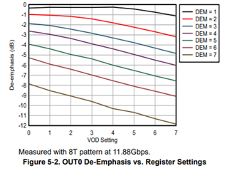
2. The IBIS-AMI model includes a model-specific parameter called VOD0.
     Is this parameter the same as the one described in the LMH0397 Programming Guide under section "3.14.1 OUT0 VOD Settings"?

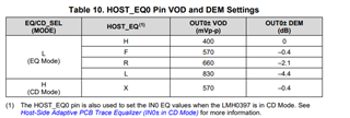
3. The documentation mentions that "Overriding Host_EQ0 pin setting enables register control of the output VOD settings." Is it possible to achieve the same VOD0 settings using the pin configuration alone, without modifying the register settings?
    My intention is to avoid basing our product design specifications on the parameter settings of the IBIS-AMI model.
    If enabling the pin and configuring it through circuit design is sufficient, we prefer not to alter the register contents unnecessarily.

Thank you for your assistance.

I look forward to your response.

Best Regards,

Diego

  • Hi Diego,

        Is my understanding correct that at operating frequencies below 3 GHz, the IBIS-AMI behavior of the LMH0397 and LMH1297 is identical, and therefore the LMH1297 model can be used as a substitute for the LMH0397?

    Your understanding is correct.

    The IBIS-AMI model includes a model-specific parameter called VOD0.
         Is this parameter the same as the one described in the LMH0397 Programming Guide under section "3.14.1 OUT0 VOD Settings"?

    Yes, this understanding is correct as well.

    . The documentation mentions that "Overriding Host_EQ0 pin setting enables register control of the output VOD settings." Is it possible to achieve the same VOD0 settings using the pin configuration alone, without modifying the register settings?
        My intention is to avoid basing our product design specifications on the parameter settings of the IBIS-AMI model.
        If enabling the pin and configuring it through circuit design is sufficient, we prefer not to alter the register contents unnecessarily.

    You can use pin mode note that the difference between the two is that with pin control there are four fixed settings that affect both VOD and de-emphasis, whereas with register control and IBISAMI settings it is possible to individually adjust VOD0 (using IBISAMI terminology) and DEM0.

    See Table 10 in the LMH0397 datasheet for more information on the VOD and DEM values and their corresponding pin setting in EQ mode.

    Best,

    Nick

  • Hi Nick,

    Thank you for your response.

    I have an additional question regarding your last answer:

    I searched through the documentation but couldn't find information that correlates the VOD0 values to mVp-p or the DEM0 values to dB.

    Could you please point me to where this information is documented?

    Regarding VOD0, the datasheet mentions that the output voltage varies from approximately 400 to 1000 mVp-p.

    Based on this,I expected the VOD to increase in steps of about 85.7 mVp-p (calculated as (1000– 400) / (8 – 1) ).

    However, in ADS simulations, the VOD increased in steps of about 100 mVp-p.

    For DEM0, I couldn't determine the range or the step sizes from the documentation.

    Thank you for your assistance.

    Best regards,

    Diego

  • Hi Diego,

    For VOD0, you are correct in that the output voltage varies from approximately 400 to 1000 mVp-p. The range is approximate, so the minimum may be slightly above 400 and the maximum is usually above 1000. From what I simulated, the difference in voltage from VOD0 = 0 to VOD0 = 1 is close to the 85.7 mVp-p change you mentioned above. It should be ~85 mV p-p typically depending on part to part variation.

    The DEM range is designated from 0-7 in the LMH1297 IBIS AMI user's guide.

    See this example from the LMH1229 programming guide to get an idea for the step sizes of the DEM0 setting. As you can see, the step size varies.

    Best Regards,

    Nick

  • Hi Nick,

    Thank you for your detailed response and for clarifying the approximate range and step sizes for VOD0 and DEM0.

    The information you provided has resolved my questions.

    I appreciate your assistance.

    Best regards,
    Diego