This thread has been locked.

If you have a related question, please click the "Ask a related question" button in the top right corner. The newly created question will be automatically linked to this question.

THVD1420: Glitch on line when changing directions

Part Number: THVD1420

Tool/software:

Hello:

We had some questions about an issue we are having with a system using the THVD1420 that we would be helpful to receive guidance for.

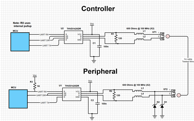
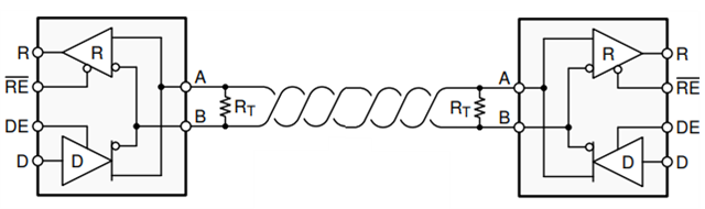
We have a device with two PCBs communicating via RS485 using the THVD1420. There is only two nodes in the interface - a controller and a peripheral, connected with a cable of around 1 meter. We use the same schematic as the one from section 8.2.2 of the datasheet.

Our system looks like this:

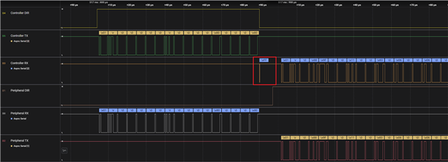
When communicating, the controller queries the peripheral with a message, and the peripheral replies with a response. The communication is always starter by the controller. When the controller sends data, it then starts to listen immediately on the line.

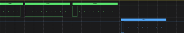
The issue we are having is that when the controller changes its direction pin from sending to receiving, the line is now idle, and there is a small glitch that makes the controller think it received a byte when it really did not. This small idle time is seen as a start bit by the UART peripheral of the MCU. This happens 90% of the time, which makes it difficult to just throw away the first bit received.

The write and read are controlled via DMA so it is hard to add a delay before reading (the DMA of this MCU is such that a TX+RX action chain can be defined as a single work unit).

My question is, what can we do to mitigate this issue? I was under the impression that the THVD1420 has fail safe resistors that should help with idle bus issues. Could it be that we need stronger resistors? Other than this issue, our communication at 2MBPS is very reliable, so I am doubting it could be an impedance mismatch between the cable and terminating resistor. But I could be wrong!

Below is a capture of the communications. I circled in red the glitch that happens when the controller changes from sending to receiving.

Any help on this is greatly appreciated!

Thank you,

-Eduardo Garcia

  • Hi Eduardo,

    This is actually an issue common to most RS-485 transceivers. The problem is that the bus has enough capacitance on it such that the voltage levels are still settling when the receiver is turned on. The device is switching from transmitting to receiving data fast enough such that it is reading the last bit that it sent out itself. 

    There are a two primary solutions for this:

    • If you have individual control of the transmit/receiver modes, then simply add a small delay in between transmitting and receiving. This allows the bus enough time to stabilize (if you have the DE and /RE pins shorted together this may not be an option). 
    • The other solution is to have the last bit on the controller TX be a voltage high signal. Rather than waiting for the bus to stabilize back to a high voltage, the controller helps it stabilize by sending that voltage signal. 

    If this does not fix your system, please send a schematic, and I would be happy to review this as well. 

    Best regards,

    Ethan

  • Hi Ethan,

    Thank you for your help! We tried sending a last byte of 0xFF (to be ignored by the peripheral) but it seems we still have this issue. Did I understand correctly your suggestion? Please let me know if I didnt!


    Unfortunately we do not have individual control of the RE and DE pins. Could this be indicative of anything else happening?

    I forgot to mention, but we are using a 8 bit, no parity, 1 stop bit setting.

    Thank you!

  • That is very interesting. Sending 0xFF on TX should fix it, but there might be something else interfering then. I have actually simulated this glitch myself in the past as it is a common problem. However, holding TX high (or 0xFF in your case) always solved the issue for me. 

    Have you added additional filtering capacitors to the bus? If you could send a schematic of the design I could also verify everything is working as expected.

    Regards,

    Ethan

  • Thank you. I unfortunately cannot share the schematic directly, even if simple, due to company policies. Would it be ok to email it to you?

  • Hi Ethan:

    Here is an schematic of our current system.

    Thank you!

  • Hi Eduardo, 

    I sent you a friend request so you can private message me through E2E. We can exchange emails there if you like. 

    I have a couple more suggestions:

    • Would it be possible to provide scope shots of the glitch rather than logic analysis plots? It would be helpful to see more detail around the glitch state, specifically how long it is. 
    • Consider tying a small capacitor from the R output pin to ground (around 15-50pF should work). This might filter out the glitch but this depends on the glitch duration. 
    • If you have the ability, try testing without the ferrite beads L1-L4. 

    Regards,

    Ethan

  • Hi Eduardo,

    Just following up on this issue you are having in case you still need assistance. Were you able to resolve the glitch?

    Best,

    Ethan

  • Hi Ethan:

    Thank you for your follow up. I was about to reply to this message. The removal of the ferrite beads does seem to fix the issue. Thank you!