Tool/software:
Hi,
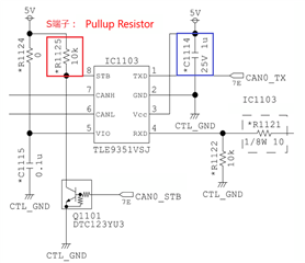
In the current circuit shown below, we are considering changing the CAN transceiver from INFINEON to TI.
・Current product: TLE9351VSJ
・Changed product: TCAN1051HGV

Question 1
About the connection circuit for the S terminal
In the current connection circuit, a pull-up resistor and a transistor are connected to the S terminal. When "Hi" is input, it is thought that the pull-up resistor and the pull-down resistor inside the IC will be connected to a voltage divider. So please tell me either of the following information.
・The min/max value of the pull-down resistor inside the IC
・The min/max value of the pull-up resistor that can be connected
Question 2
Looking at the data sheet, it is recommended to connect "4.7uF + 0.1uF" as a bypass capacitor for the Vcc power supply terminal, but currently the recommended capacitance for INFINEON ICs is 1uF. Could you please comment on whether it would be a problem in terms of IC specifications if the IC was replaced with the current capacitance?
If it is difficult to judge whether the above is possible or not, we would like to make a judgment by actual measurement. Is it okay to check the Vcc power supply voltage waveform during bus communication with the current capacity, and determine that there is no problem if the voltage fluctuation (including ripple) is within the recommended operating range?
Thanks,
Conor

