This thread has been locked.

If you have a related question, please click the "Ask a related question" button in the top right corner. The newly created question will be automatically linked to this question.

SN65HVD77: termination resistor and series resistor for protection

Part Number: SN65HVD77


Tool/software:

Hello, 

In the SN65HVD77 DS are represented two different scenario, accordig to the following figures:

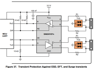
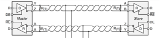
My question is how merge the two design, the termination resistor R(T) and R1? Which is the resulting scheme? 

the R1 resistor near connector? or the R(T) near connector? In case of the R1 equal to 10Ohm the termination resitor R(T) value needs to be adjusted consequently? 

A split termination and common mode filter can be an effective way to increase the system robustness?

Thank you,

BR

  • The left figure shows examples for some protection components. The right image shows that termination resistors must be placed only at the two ends of the bus.

    In general, the protection components should be placed near the connector, and the termination resistor near the transceiver's pins.

    The left figure is just an example, split termination and common-mode chokes indeed are possible additions.

  • Hi Luca,

    If you want to merge both designs, place the termination resistor closest to the transceiver with the series resistors after it closest to the connector. The R1 and R2 should be 10 Ohm pulse-proof resistors otherwise series resistors above 10 Ohms are not recommended. 

    Only the two farthest end nodes should be terminated. R_T should be 120 Ohms and does not need to be adjusted if R1 and R2 are small. 

    Split termination and a common mode choke can both be used to increase system robustness. I would also recommend ESDS552 for the ESD diode. 

    Best,

    Ethan