This thread has been locked.

If you have a related question, please click the "Ask a related question" button in the top right corner. The newly created question will be automatically linked to this question.

SN55LVDS31-SP: How to use in multidrop system

Part Number: SN55LVDS31-SP
Other Parts Discussed in Thread: SN55LVDS31

Tool/software:

Hi Team,

One of my cusotmer wants to use SN55LVDS31 & SN55LVDS33 in their systems. They have raised few queries.
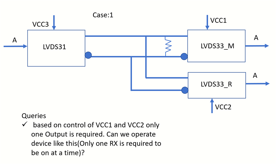
Case - 1:- 

What happens in case 1 if 2 drivers are connected to one receiver? Is it allowed? If not what is the issue? Note that only one driver will be active at a time.
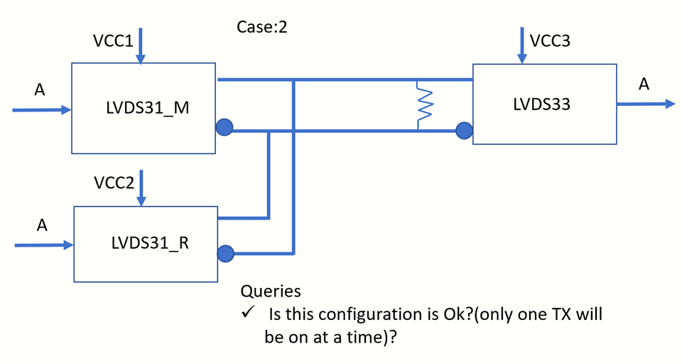
Case 2:-

For case 2, there will be two receivers & one transmitter. What happens in this case? Only one Rx will be active at a time?

For both the case it might happen that one device is in OFF state (not powered), what happens in this case?

Regards,

Mitesh

  • Hi Mitesh,

    Case 1 is not a standard LVDS configuration - a multi-drop configuration per the TIA/EIA-644 LVDS standard only allows one transmitter with up to 32 receivers. If configured this way with only one transmitter transmitting, special consideration to the stub length is required to prevent excessive signal reflections and bus ringing. Although it is mentioned only one transmitter will be on at a time, please note that if a case occurs where two transmitters are on, contention issues may arise along the bus and devices may be damaged. You may consider looking into using a half-duplex MLVDS configuration as an industry standard alternative.

    Case 2 is a standard multi-drop LVDS configuration (a single driver + bus with two or more receivers (up to 32 receivers) ). Again, it is recommended to give special consideration to the stub length to prevent excessive signal reflections and bus ringing. 

    Another thing to note here - ensure that the supply voltages listed for each device have a common ground connection, specifically if you plan to have these devices on separate EVM's. There should be no issues in terms of devices in the off state, as long as stated datasheet maximums are not exceeded.

    Sincerely, Amy

  • Hi Amy,

    Just want to confirm for case 1 in which there are 2 transmitter output shorted together. For this case if one transmitter device is in off state and one transmitter device is ON state, is there any reliablity concern?

    What happens to OFF state device?

    What happens to ON state device?

    For customer use case they have two seperate cards where they want to implement redundency so assume that one card is non biased and one card is biased where these LVDS transmitter are mounted.

    Also note that MLVDS is not the option as customer need space grade solution. I belive for transmotter section LVCP22 is the only solution. Pls share your inputs.

    Regards

    Mitesh

  • Hi Mitesh,

    Amy is currently out of office. I have some experience with these devices so I can provide some comments.

    Just want to confirm for case 1 in which there are 2 transmitter output shorted together. For this case if one transmitter device is in off state and one transmitter device is ON state, is there any reliablity concern?

    What happens to OFF state device?

    What happens to ON state device?

    Ideally, you shouldn't have two transmitters on and active at the same time since they could get into contention with one another resulting in bad data. If you powered one off and the other one stays on, there shouldn't be any problems with either of them as long as the absolute max ratings of the device aren't exceeded/broken.

    These devices have a transmit disable feature so you could technically have both on but only enable one set of drivers. 

    -Bobby

  • Bobby,

    Datasheet is not showing any absolute ratings for output and hence asking for the clarification. Since thisv requirement is for Space application, I want to make double sure that if two transmitter of two different devices are in parallel and one of the device is in non biased, is there any reliablity concern?

    Note that we are not talking about two transmitter of same device.

    Regards

    Mitesh

  • Hi Mitesh,

    Thanks for clarifying the abs max isn't actually stated in the datasheet (I didn't realize this was the case). I think this is because in a normal system the LVDS driver is the only driver on the bus (usually just one of them) and there isn't normally an external voltage on the bus with one driver present. 

    I looked at some of the other MLVDS devices with the spec called out on the abs max, it looks like it's 4V (they should use the same FET process nodes which is why I looked at the MLVDS drivers) which matches the Vcc abs max for this device as well. Since the device calls out one the first page that it is high impedance when the Vcc is isn't present ("Driver at High Impedance When Disabled or With VCC = 0") it shouldn't back bias when it sees an external voltage applied to it's outputs. I believe the abs max on the A/B pins should be +4V here. 

    -Bobby