Part Number: TCA6424A
Tool/software:
◆Question
1.Are "Polarity Inversion Registers" registers that can invert the polarity of only the input ports?
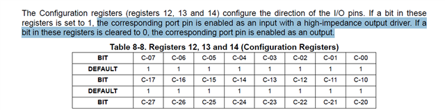
2.Are the "Configuration Registers" registers that can only be configured for output ports?
Also, could you please tell me in what specific cases these settings are necessary?
Best regards