TMUXHS4212: Supporting peripheral for the CC pins

Part Number: TMUXHS4212
Other Parts Discussed in Thread: TUSB320, TUSB321

Tool/software:

Hello,

For this design i have no issues related to USB3 signal lines. For the SEL pin in mux coming from the CC1/CC2 pins of the connector. I figured it needs CC controller but I am implementing by using dual NOR gate circuit as I don't want PD from it just data transfer is fine.
And, the CC lines are pulled down before going to the logic gate.

So, is using the logic gate to determine the SEL lines of the mux a correct approach ?

  • Hello,

    This isn't an implementation that is common, or at least I have seen before, so I can't say for sure if its correct necessarily. If doing this allows you to control the mux as you need then I don't see any reason why it would not be okay. Though typically, we do see either a PD controller, or a CC controller. If you're using these logic gates just to control the SEL pin, maybe a CC controller could do the same? https://www.ti.com/product/TUSB320

    Please let me know if you have any other questions.

    Thanks,

    Ryan

  • Hello,
    Can i know the connection between TUSB320 and TMUXHS4212. 

    Thank you

  • Hello,
    I am not using MCU. So, I want the CC controller to be operated independently if I just get power for the USB connector.

  • Hello,

    Sorry, actually I meant to recommend the TUSB321.

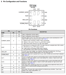
    The TUSB321 would not require any MCU to control it. The TUSB321 would read the CC pins from the connector once a type-c connection is made, and depending on the signaling from the CC pins, the DIR pin of the TUSB321 could be used to control the SEL pin of the TMUXHS4212.

    No MCU is required. Additionally, if needed, the TUSB321 can be powered by VBUS.

    Thanks,

    Ryan

  • Hello,
    Can I get the connections to be made between CC controller and mux for it to work as DRP mode.

    Should the DIR pin be pulled up when connecting to SEL pin on the mux, or can it be connected directly ?
    And the ID, VCONN_FAULT, and OUT pins be unconnected and i want it to be in DRP mode so, the PORT pin is also NC.
    As mentioned there would be connected the connectors of USB type C, mux, cc controller, these are powered on based on the VBUS voltage, Is this approach correct ?

    Thank You.
     

  • Hello,

    Can I get the connections to be made between CC controller and mux for it to work as DRP mode.

    The only connection needed between the CC controller and the mux is the DIR pin being connected to the SEL pin. As DRP, the TUSB321 itself will toggle between DFP and UFP until a connection is finally made, at which point the DIR pin will control the SEL pin.

    Should the DIR pin be pulled up when connecting to SEL pin on the mux, or can it be connected directly ?

    This can be directly connected, no pull-ups needed.

    And the ID, VCONN_FAULT, and OUT pins be unconnected and i want it to be in DRP mode so, the PORT pin is also NC.

    If you have no need for the functionality of those pins, yes, they can be left NC. Please make sure VBUS_DET is correctly connected, however.

    As mentioned there would be connected the connectors of USB type C, mux, cc controller, these are powered on based on the VBUS voltage, Is this approach correct ?

    For a DRP connection, an external voltage rail needs to be used. VBUS can only be used in a UFP connection, that's my mistake, sorry about that. For DFP and DRP, it is recommended to have an external 4.5-5.5V Vdd.

    Please let me know if there are any other questions.

    Thanks,

    Ryan

  • Hello,
    Thanks for the detailed information.
    For VBUS_DET should be connected through a resistor or is the direct connection fine ?
    For default current mode, I am leaving it unconnected is that fine or should i connect it to ground ?
    Can I share the schematic in personal if possible ?

    Thank You

  • And, I am not sure if it would be UFP or DFP, hence the PORT pin is being left unconnected, is that fine ?

  • Hello,

    For VBUS_DET should be connected through a resistor or is the direct connection fine ?

    A 900KOhm resistor is required to be connected to VBUS to ensure proper operation.

    For default current mode, I am leaving it unconnected is that fine or should i connect it to ground ?

    For default current, you can leave it floating.

    Can I share the schematic in personal if possible ?

    Yes, you can send over the schematic if needed. You can either post it here, or send me an E2E friend request and then PM it after I accept.

    And, I am not sure if it would be UFP or DFP, hence the PORT pin is being left unconnected, is that fine ?

    Yes, the PORT pin being floating is recommended for DRP.

    Please let me know if you have any other questions.

    Thanks,

    Ryan