THVD1450: Schematic Review Support

Part Number: THVD1450
Other Parts Discussed in Thread: MAX3221

Tool/software:

Hi expert,

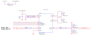
Customer used our THVD1450 and MAX3221I. May I have your support to review the schematic and let us know if any comments? 

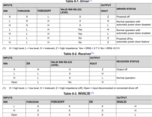
Please also clarify the Auto-Powerdown Plus (disable/power off feature) is implemented appropriately cause we are not clear from the true table below. 

Customer's intension is to use minimum e.g. one pin to let RS232 shutdown when no data communication. 

Regards.

Allan

  • The RS-485 circuit looks OK.

    On the MAX3221, pin 8 (RIN) is the RS-232 bus input, and pin 9 (ROUT) is the logic output for the SoC.

    The MAX3221 limits the output slew rate to less than 30 V/µs; capacitors on the RS-232 are not required (but do not hurt). Ensure that all capacitors are connected with traces that are as short as possible.

    The /EN pin disables only the receiver. As far as I know, it does not affect the power consumption.

    When /FORCEOFF is low, then the driver is disabled.
    When /FORCEOFF is high and FORCEON is high, then the driver is always enabled.
    When /FORCEOFF is high and FORCEON is low, then the driver is enabled only when the RS-232 port is connected to a PC. (It is assumed that the PC's RS-232 port always outputs a valid signal.)

  • Hi Allen,

    Clemens comments are correct.

    The only thing I would add is I usually like to tell customers to put pull up resistors (like 10k) on the D and R pins of the RS485 TTL sides. Customer can have them as do not populate (DNP) if they don't need to use it. 

    Same thing for the RS232 TTL input, I usually like to tell customers to add pull ups on the Din pin. They can be do not populate as well if they don't need it.

    -Bobby

  • Hi Clemens,

    Make sure FORCEON is low when RS232 bus we don't need using, it can save more power consumption, and the other pin like /EN, /FORCEOFF doesn't affect the power consumption, am I right ?

    Would mind explaining the advantage of using the auto shutdown features?

    Customer want to know the details, it can help them to save GPIOs using.

  • Hi Bobby,

    Would you tell me the pull up resistors using situation ?

  • Would you tell me the pull up resistors using situation ?
    The only thing I would add is I usually like to tell customers to put pull up resistors (like 10k) on the D and R pins of the RS485 TTL sides. Customer can have them as do not populate (DNP) if they don't need to use it. 

    In a situation where the receiver is disabled, the R pin will float. If this happens the MCU/Processor will be connected to the R pin which can then cause a start condition or break condition because the R pin floated to GND. Populating the pull up resistor on R here would fix the problem. 

    If you connect the D pin to a processor/MCU but the pin is high-Z and doesn't get configured until it is initialized later, the high-Z pin looking like a floating input for the D pin which can cause the same issue as above where you send a start condition or a break condition on the D pin which gets sent through the RS485 transceiver if it is enabled. Putting a pull up resistor here would resolve this. 

    Same thing for the RS232 TTL input, I usually like to tell customers to add pull ups on the Din pin. They can be do not populate as well if they don't need it.

    The same concept I described for the D pin for the RS485 applies here. I've seen this happen with a customer because they have the D pin floating when the MCU/processor is not set as an output so the D pin floats and causes garbage data on the RS232 line. A pull up resistor fixed the issue.

    Make sure FORCEON is low when RS232 bus we don't need using, it can save more power consumption, and the other pin like /EN, /FORCEOFF doesn't affect the power consumption, am I right ?

    Would mind explaining the advantage of using the auto shutdown features?

    If you set forceon low and force off high, the device can enter the low power mode saving current. This occurs when RIN's voltage is between -0.3V and 0.3V  for longer than 30us. The situation this occurs is when the RS232 transceiver is not connected through a cable to another RS232 transceiver that is enabled. It will exit the power savings mode when the RIn pin is brought outside of the -0.3V to 0.3V range, this would occur when it is connected to another RS232 transceiver through a cable when the other RS232 transceiver is actively driving a signal.

    -Bobby

  • Hi Bobby

    I modify the schematic base on your suggestion. I also mark the signal of RS232 and RS485 source and destination, please help to review it.

  • Hi Cooper,

    The circuits look okay to me. 

    One last thing you can add on the RS485 side is external fail safe resistors. Customer probably won't need it but it's nice to have if there is noise on the bus when its idle. It can help add some noise immunity. You can do this by putting a pull up resistor on A and a pull down resistor on B. You can set the value to 1k ohms and set it as a do not populate (DNP).

    -Bobby