


Other Parts Discussed in Thread: TCA6424A, TMAG5231
Tool/software:
Hello,
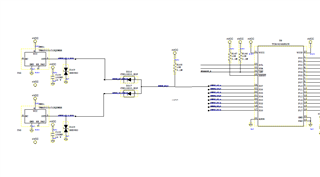
I have a circuit in which I have 2 TMAG5231 sensors connected in a diode-or configuration and the output is going to a pin of the TCA6424A. The or circuit has an 10k external pullup such that when the TMAG sensor is active, the TCA6424A pin pulls low and when the sensor is inactive the 10k pullup resistor pulls it high (please refer to the diagram shown below). both VCCI and VCCP are tied to the same 3.3V source. I have multiple of such sensors connected in the same configuration and it works as expected.
on some sensors the PCBA house did not install the 10k resistor but even then I can see VCC on the TCA6424A pin when the sensor is not active and is pulled to gnd when the sensor is active indicating that it has some sort of an internal weak pullup. I measured the resistance between the VCC and the pin of the TCA6424A and it shows around 345K. is this expected?
I am going to add the pullup going forward but I am curious to know where this leakage path is coming from. also what is the max value of this resistor pullup I can use and still get reliable operation? I have 24 of such circuits and when all 24 paths are active, the effective resistance is around 416ohms (24 10K resistors in parallel) increasing the current draw to around 8mA. I need to minimize this current draw by increasing the value of the pullup resistor.
Thank you.
