Part Number: TUSB216EVM
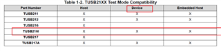
Other Parts Discussed in Thread: TUSB216-Q1, TUSB216,
Tool/software:
Hi team,
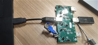
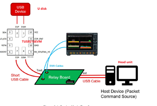
In the test scenario, the customer connected the USB of the head unit to TUSB216-Q1, but the eye diagram was not improved as found from the oscilloscope. The test scenario is as follows:


At first, the TUSB216 was powered by 5V of VBUS, but it didn't work. Then we decided to separate the TUSB216 and use a separate power supply. Although the CD light on the board was on, the eye diagram was not improved.
Let me explain why the customer did not use a fixture. The customer software set a strategy that would stimulate the Head unit to continuously send USB2.0 data packets as long as an external USB device was inserted for testing.
The operational suggestions I give to customers are the same as those given by Ryan before:
Here is the full test procedure. It's important to follow it step-by-step.
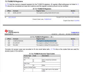
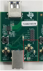
- Configure the TUSB216 to the desired BOOST setting
- Power on (or toggle the RSTN pin if already powered on) the TUSB216
- Using SMA cables, connect the oscilloscope and the USB-IF host-side test fixture to the TUSB216. *You may also disconnect/reconnect the USB cable from board if already attached.
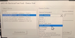
- Enable the host to transmit USB TEST_PACKET
- Execute the oscilloscope USB compliance software.
- Repeat the above steps in order to re-test TUSB216 with a different BOOST setting (must reset to change)
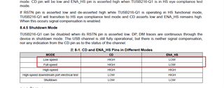
During the test, CD was measured as high level and EDA was measured as low level. We judged that HS was not triggered.
Do you have any more suggestions for the issues that the customer is currently testing? Looking forward to your professional advice.