This thread has been locked.

If you have a related question, please click the "Ask a related question" button in the top right corner. The newly created question will be automatically linked to this question.

TCAN1043A-Q1: Some questions about datasheet

Part Number: TCAN1043A-Q1


Tool/software:

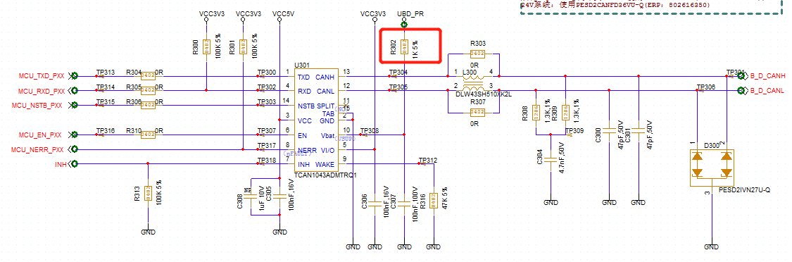
1.Considering that the Vsup voltage is high (the current requirement is less than 130uA), the fluctuation of Vsup may cause large crosstalk in adjacent signals, and 1k series resistance is generally considered (as shown in the figure below).

Then will the chip have a surge in Vsup current demand (large increment), making the chip Vsup below the undervoltage threshold?

2.For sleep mode (caused by SWE timer overflow), tmode1 is the minimum time that the nSTB needs to remain low after the EN edge, but can the EN not perform a level shift (for example, EN (L→H )is required, and the EN is already low when it enters sleep)? Is this level switch before tmode1(red mask) necessary?

3.If the standby device enters the go-to-sleep system, WAKERQ is required to be cleared. However, the datasheet mentions that only UVCC/UVIO/transition to normal mode will clear WAKERQ.

However, considering that UVCC/UVIO causes CAN to become sleep-mode in any-mode, there is only one remaining way for WAKERQ to be cleared (that is, converting CAN to normal-mode), which contradicts putting CAN into go-to-sleep mode.So what to make of the WAKERQ clear?

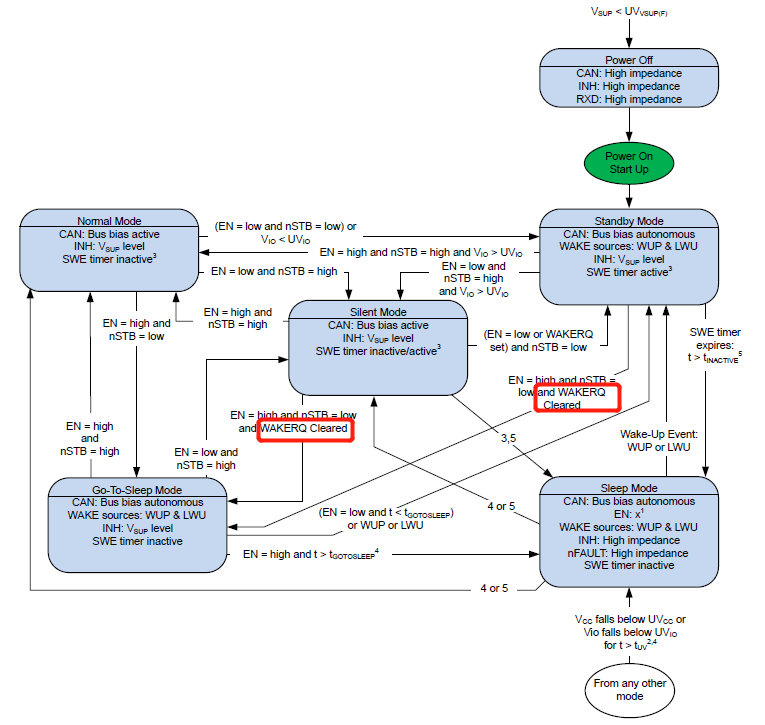
4.The undervoltage of the VCC VIO needs to be undervoltage longer than the tUV. So voltage recovery also requires normal voltage to maintain tUV?

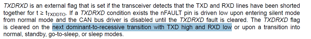
5.In the condition of TXDRXD flag clearing (8.3.7.1.7), the REC-DOM transition means that TXD is performing a REC-DOM transition? Or does it mean that a TXD or RXD performs a REC-DOM,transition?(that is, in silent-mode,a REC-DOM transition through the RXD (read-back bus) can  pull up nFAULT by clearing the TXDRXD flag)?

6.PWRON, WAKERQ, and WAKESR are set for the first power-on.So for wake up source recognition, is the first power-on considered a local wake?
Besides, does initial power up means cold start?

7.There is a concept of "4 consecutive DOM-REC transitions" regarding the time requirement for clearing and setting bus fault flag bits, but the datasheet also gives tCBF data. There may be some difference between the two figures. Which one shall prevail?
(For example, if the 8-bit data switch 8M rate is used, the time of the 4 consecutive edges will be less than 1/8M*10^6*8=1us; The min of tCBF in the datasheet is 2.5us)

  • Hi Yunmiao,

    Thanks for reaching out.

    We currently have a surplus of support questions, but I will try to get a response to you by the end of day tomorrow. 

    Best,

    Ethan

  • Hi Yunmiao,

    These are good questions. 

    1. From my experience, I have not seen or heard of a surge in current causing the device to enter the undervoltage threshold. This depends largely on your VSUP voltage and the magnitude of VSUP fluctuation you are anticipating. If this is a concern or you have seen issues with this, the 1K series resistor can be left off as it is not required.

    2. If I understand your question correctly, switching EN from L->H before tMODE1 is not necessary for the transition from Sleep to Normal mode. EN must be low for time tMODE1 then nSTB can go L->H. Then the last step to enter Normal mode is to raise EN high. If EN is already low, then just ensure EN is high after nSTB goes high.

    For Sleep to Silent, EN must be high for time tMODE1. Then nSTB can be high and the EN H->L transition can take place.

    3. It is correct that transitioning to Normal mode or an undervoltage condition for VCC or VIO will clear the WAKERQ flag. I am not sure I understand this question fully, but I will try to explain the purpose of WAKERQ.

    The Wake-up request is triggered in three ways: device starts up from a cold start, Wake-up event from CAN bus (WUP), Wake-up event from WAKE pin (LWU). The device is designed so that it cannot accidentally enter Go-To-Sleep Mode (then Sleep mode) from Standby after it has received an important request like a CAN bus wake-up. Entering Normal mode will clear this flag/request as well as the undervoltage threshold for VCC and VIO.

    Normally VCC and VIO should not go below the threshold unless there is a supply issue or specifically designed by the controller/PMIC. Entering Normal mode is the main way WAKERQ should be cleared.

    4. VCC and VIO voltage recovery is defined by tUV(RE-ENABLE) in the datasheet. The datasheet defines this as a max of 200us.

    5. Because the device is in Silent mode when the TXDRXD flag is active, the CAN bus driver is disabled. So TXD is not responsible for the dominant-to-recessive transition. This transition must come externally from the CAN bus.

    6. First power-on is not considered a LWU (local wake-up) if that is what you are asking. Initial power up and cold start mean the same thing.

    7. tCBF is not the time to clear the flag, but rather the minimum time necessary to detect a bus fault. This time of 2.5us would prevail.

    Regards,

    Ethan

  • Hi Ethan,

    3. It is correct that transitioning to Normal mode or an undervoltage condition for VCC or VIO will clear the WAKERQ flag. I am not sure I understand this question fully, but I will try to explain the purpose of WAKERQ.

    The standby switch to go to sleep is one of the conditions: WAKERQ cleared. How is WAKERQ cleared achieved?(UVCC?UVIO?Or some other way?)

    5. Because the device is in Silent mode when the TXDRXD flag is active, the CAN bus driver is disabled. So TXD is not responsible for the dominant-to-recessive transition. This transition must come externally from the CAN bus.

    When the TXDRXD flag is active and the chip is still in normal-mode, the receiver is working properly and the transmitter of the faulty node is disabled. If the bus is occupied by another node, will the TXDRXD flag of the faulty node be cleared?

    New question:

    The bus fault failure circuitry has requirements for RCBF and tCBF, and in the RCBF datasheet is 45~70Ω, but in the condition of RCM=RL=60Ω, in order to avoid reflection, the differential impedance should be about 120Ω? Or can you draw RCBF and RCM in the same diagram (to represent their connection)?

    Best wishes,

    Yunmiao

  • Hi Yunmiao,

    Ethan is currently out of office until the new year. Sorry for the delay but you can expect a reply by Jan 6th.

    -Bobby

  • Hi Yunmiao,

    WAKERQ will be cleared when VCC < UVCC or VIO <UVIO. So when either VCC or VIO drop below the undervoltage lockout threshold for time tUV, this flag will be reset and cleared. As Table 8-1 states, WAKERQ can also be cleared by entering Normal mode. 

    For the TXDRXD flag, if the flag is active then the device will be in Silent mode, not Normal mode. But you are correct that the receiver is active and the transmitter/driver is disabled (this is what Silent mode is). The other nodes will not know that the TXDRXD flag has been raised so they will continue to operate normally. In order for this faulty node to clear the TXDRXD fault please reference Table 8-1 in the datasheet. 

    For a properly terminated CAN bus, there would be two 120 Ω resistors at the farthest ends of the bus. Because there are two of these resistors, they are actually in parallel, leading to a resistance close to 60 Ω. In this case the RL would still be inside the RCBF range. 

    Best,

    Ethan

  • Hi Ethan,

    For the TXDRXD flag, if the flag is active then the device will be in Silent mode, not Normal mode. But you are correct that the receiver is active and the transmitter/driver is disabled (this is what Silent mode is). The other nodes will not know that the TXDRXD flag has been raised so they will continue to operate normally. In order for this faulty node to clear the TXDRXD fault please reference Table 8-1 in the datasheet. 

    Local Faults flags(TXDCLP、TXDDTO、TXDRXD、TSD) will cause the chip to switch directly to silent-mode without requiring the MCU to do so (EN = low and nSTB = high)?

    New question:

    1. The undervoltage time is not mentioned in the mode conversion of the transceiver, such as the undervoltage in CAN Active and CAN Autonomous. Is it not necessary for the undervoltage time to exceed the tUV?
    If in any mode, will the VCC undervoltage (time does not reach the tUV) cause the chip to stay in the original mode and go to sleep-mode after the tUV?

    2.VIO undervoltage, does it directly switch to standby no matter what mode it is in, and then go to sleep-mode after tUV?
    Or is it only normal that goes to standby first, and then goes to sleep-mode after tUV?

    3.If wake-up is disabled in silent-mode, how to set WAKERQ(for  silent -> standby)? [Only standby -> silent (not go through normal)?]

    4.If the VIO and VSUP are powered properly, RXD can be pulled down after the wake event. Does the nFAULT pull down (WAKERQ) also require only VIO and VSUP(no VCC power supply required)?

  • Hi Yunmiao,

    Local Faults flags(TXDCLP、TXDDTO、TXDRXD、TSD) will cause the chip to switch directly to silent-mode without requiring the MCU to do so (EN = low and nSTB = high)?

    This is correct.

    1. The undervoltage timer still applies. Before tUV the device will stay in whatever mode it is currently in. After tUV the device will directly enter Sleep mode, not Go-To-Sleep Mode. 

    2. Only if the device is in Normal mode and VIO undervoltage is triggered, the device will briefly enter Standby mode then after tUV, the device will be in Sleep mode. Otherwise, any VIO undervoltage trigger will cause the device to directly enter Sleep mode. 

    3. WAKERQ must be set prior to the device entering Silent mode. The device enters Standby mode in this way so that RXD can be brought low as an indicator of WAKERQ. 

    4. VCC power is still required. Without VCC, the device would be in Sleep mode.

    Regards,

    Ethan

  • Hi Ethan,

    4. VCC power is still required. Without VCC, the device would be in Sleep mode.

    Can it be considered that "When CAN wake up to standby mode, RXD and nFAULT will output low level (for WAKERQ)  when VIO and VSUP have normal power supply and VCC undervoltage (t<tUV), and then switch to sleep mode when VCC undervoltage (t>tUV)"?

    Best wishes,

    Yunmiao

  • Hi Yunmiao,

    Yes that is correct. After t > tUV and VCC < UVCC then WAKERQ will also be cleared.

    Regards,

    Ethan