Part Number: DP83867E
Other Parts Discussed in Thread: AWR2944EVM, AWR2944,
Tool/software:
Hi,
We have designed some custom RF and Digital boards based on the AWR2944EVM evaluation board. We have the AWR2944 radar transceiver on the RF board and the DP83867E Ethernet PHY on the Digital board, with a Samtec QTS-0 5 0-0 2-X-D-A board-to-board connector used to transition RGMII signals between the boards.
We are having issues communicating with the board over Ethernet - when we run the TDM Ethernet example provided in the SDK and enter queryLocalIP we get an IP address returned of 0.0.0.0. When running our own custom firmware we get 'link is not up' message. We have connected from the board via a router (same setup proven with AWR2944EVM board).
It seems that auto-negotiation is not happening as the clock from the MAC on the AWR2944 to the Ethernet PHY (RGMII TX CLK) is at 25 MHz speed (for 100 Mbps rate) but the clock from the Ethernet PHY to the MAC on the AWR2944 (RGMII RX CLK) is at 2.5 MHz speed.
We have tried in the firmware things like adjusting delay between clock/data (tx/rx delayInPs variable), forcing 10 Mbps speed (with auto-negotiation off) but no luck in getting it to work.
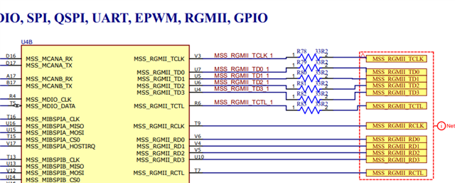
See screenshots below from board schematics:
Digital board:
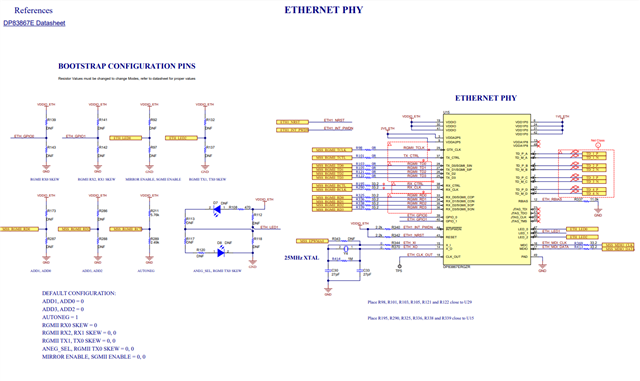
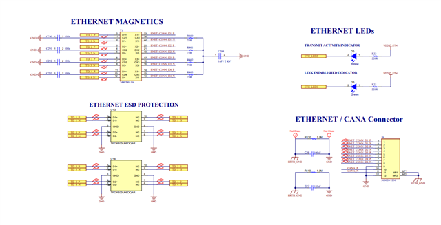
RF board: