TUSB4020BI: TUSB4020

Part Number: TUSB4020BI

Tool/software:

HI Team,

1. Any default 1.5k pull up on D+ / 15K pull down on D- to be added on the data lines of upstream port? 

2. Any cap provision (pF) on USB data lines for edge control to be added?

3. Choke will be added at upstream port close to connector. on the downstream ports can add resistors?

Thanks and Regards,

Vidhya

  • Vidhya

    Please see my response below,

    1. Any default 1.5k pull up on D+ / 15K pull down on D- to be added on the data lines of upstream port? 

    No, 1.5k and 15k are internal to the TUSB4020BI, there is no need for external pullup or pulldown resistor

    2. Any cap provision (pF) on USB data lines for edge control to be added?

    No, please do not add cap to the USB data lines as it will degrade USB signal integrity

    3. Choke will be added at upstream port close to connector. on the downstream ports can add resistors?

    Routing through ESD or common mode choke before receptacle is allowed and recommended. ESD protection should be placed as close as possible to the USB connectors. Common mode chokes should be placed between the USB hub and the ESD protection. Verify the pinout of the USB connectors. But why do you want to add CMC to the upstream port which is an input and why do you want to add resistor to the downstream ports?

    Thanks

    David

  • HI David,

    Please find my comments inline.

    1. ok

    2. In FTDI230 (USB to UART converter), it is recommended to add 47pF load caps and 27ohm series termination on D+ and D- lines. This device gets connected to DN1 ports of hub.

    3. In our case, upstream port is interfaced to USB connector. ESD protection and then choke is added between the USB hub and the ESD protection. Downstream ports DN1 is connected to FTDI chip, DN2 is connected to CPU. 

    no need to add CMC or series termination on DN1 and DN2 ports?

    Thanks and Regards,

    Vidhya

  • HI David,

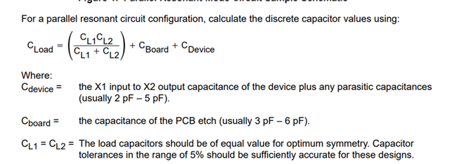
    Also in TUSB4020 EVAL schematics, load capacitance used is 18pF for the crystal.

    crystal load capacitance is 20pF (reference to datasheet). 

    But as per the reference below, 

    considering Cboard=5pF and Cdevice =3pF calculated load capacitance CL=17pF which is less than 20pF.

    how EVAL has used 18pF load caps? should it not be 22pF instead of 18pF to meet ~20pF of crystal?

    Kindly revert.

    Thanks and Regards,

    Vidhya

    Thanks,

    Vidhya

  • Vidhya

    The oscillator of the USB device may have difficulty driving a large load capacitance, so I would avoid crystal that specifies large load capacitances in its datasheet.

    In your previous response, DN2 is connected to CPU, is this a typo? I would think a CPU would act as a USB host so you would want it to connect to the hub upstream port, not the downstream port. 

    For both DN1 and DN2, you can design in CMC and series resistor as a placeholder, but populate them with 0ohm resistors. You can also design in the 47pF capacitor but choose not to populate it initially.

    Thanks
    David 

  • Hi David,

    In my case, Upstream is connected externally to a host, USB connector.

    DN1 is connected to FTDI (USB To UART) for console access via UART pins of CPU.

    DN2 is connected to serial download / flashing via USB pins of CPU.

    Crystal specs shared are from the same part used in EVAL schematics. Do you still recommend using same load capacitance value of 18pF as in EVAL?

    Recommended to add 47pF provision?

    Thanks,

    Vidhya

  • Vidhya

    The load capacitance refers to all capacitances in the oscillator feedback loop. It is equal to the amount of total capacitance seen between the terminals of the crystal in the circuit, not just the capacitance from the crystal vendor. Please keep the total load capacitance to be from 12 to 24pF as recommended in the TUSB4020BI datasheet.

    For the 47pFcapacitor, I would design it in as a placeholder but not populate it. 

    Thanks

    David

  • Hi David,

    I am using same crystal part with external 18pF load capacitance as followed in EVM.

    is it ok to not give 47pF provision on USB datalines?

    any feedback on upstream and downstream ports connection in my design?

    Thanks.

    Vidhya

  • Also, 

    USB_VBUS for self powered, 90.9K and 10K resistor divider added for P3V3.

    Regards,

    Vidhya

  • Vidhya

    47pF is an requirement from the FTDI230, I am not sure why it requires a 47pF loading capacitor since I am not familiar with this part. But my concern is the 47pF loading capacitor may slow down the DP/DM signal edge and cause eye diagram failure. For now, I would recommend include 47pF in your design as a placeholder but do not populate it. 

    For DN2 is connected to serial download / flashing via USB pins of CPU, make sure the CPU will act as a USB device in this particular case.

    Thanks

    David