This thread has been locked.

If you have a related question, please click the "Ask a related question" button in the top right corner. The newly created question will be automatically linked to this question.

THVD1439: Surge protection & grounding guidance

Part Number: THVD1439
Other Parts Discussed in Thread: THVD1400

Tool/software:

Hello E2E Community,

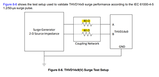
We seek your inputs & clarification on following queries in regards to the IEC 61000-4-5 Surge testing of the THVD1439

  1. Why is there a 80Ohm coupling network - what does this imply?
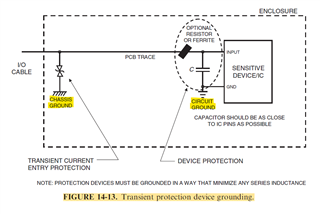
  2. The datasheet further suggests a layout - my question - is it okay to connect the TVS coupled ground pin to the digital ground on the PCB?
  3. Is dumping the surge transients current in the main circuit digital ground a good approach?
  4. Can I simply connect the THVD1439 ground to chassis ground which is at one point connected to the digital ground - thereby minimizing the surge transients on the digital ground?

We will also install a 15Ohm pulse rated series current limiting resistors on both A & B - with objective to further reinforce the surge transient robustness by reducing the current entering the transreceiver.

  • 1. The 80 Ω resistors are from the IEC specification. I can neither confirm nor deny whether this is an accurate simulation of your actual circuit.

    2. The datasheet suggests to connect the GND pin to the ground plane, i.e., to the digital ground.

    3. The currents should be dumped into some large-enough capacitor, and usually, the decoupling capacitors on the supply rails are all you have.

    4. Any long trace has a certain inductance and might encourage the transients to jump somewhere else. You should have a decoupling capacitor at the same place as the protection component. The THVD1439's internal TVSes dump the current into the VCC/GND decoupling capacitor that you should already have; if the connector is some distance away and you have other protection components there, then it might make sense to add a capacitor there (on whatever power rails you're using there).

  • Why is there a 80Ohm coupling network - what does this imply?

    Clemen's already answered this but this is just called out by the standard.

    The datasheet further suggests a layout - my question - is it okay to connect this to the digital ground on the PCB?

    That should be fine. Some customers separate digital and analog GNDs when they require isolation. RS485 devices can drive higher amounts of current (around 50mA per driving channel) so some customer choose to separate them.

    Is dumping the surge transients current in the main circuit digital ground a good approach?

    I should point out that for the surge tests, we use a decoupling network on the power supply. I believe it's something like a 30mH inductor on the GND and Vcc to ensure the transient current doesn't rush into the power supply and break something. Instead we want it to go back into the surge generator. We also put fuses infront of the inductor incase the inductor is too slow to respond to block the transient.

    Can I simply connect the THVD1439 ground to chassis ground which is at one point connected to the digital ground - thereby minimizing the surge transients on the digital ground?

    Yes, I believe this should be fine... if you have a way to minimize the transient current going into the digital GND, I believe it's best to do so. It's better for the current to go back into the surge generator.

    You can take a look at this document which goes over surge protection design for RS485: https://www.ti.com/lit/ug/tiduas1b/tiduas1b.pdf?ts=1735264661090

    -Bobby

  • Hello  & @BOBBY,

    The reason for our confusion is also highlighted in following from Henry Ott's text - we are currently using THVD1400 & have added the TVS as shown in the following figure & have had a properly functional system. 

    The THVD1439's internal TVSes dump the current into the VCC/GND decoupling capacitor that you should already have; if the connector is some distance away and you have other protection components there, then it might make sense to add a capacitor there (on whatever power rails you're using there).

    With new THVD1439 - I am unsure how to separate the Digital ground & the Chassis grounds - physically we can - but electrical implications are not very clear as digital ground (ie the circuit ground in following figure) shall be carrying active signal currents which we do not want to be part of the chassis ground - kindly suggest if the MLCCs on the Vcc to Gnd of the THVD1439 might be sufficient to help minimize the upset due to dumping of the transient on digital/circuit ground?

    We have MCU & EEPROM on the same PCB & the size of the PCB is small 45mmx35mm.

    Can we add additional decoupling MLCCs like 3x 0603 100V rated MLCCs on the Vcc to GND of the THVD1439 to improve the transient dampening that is shunted by the internal TVS? Or do we add a 100pF 2kV rated MLCC to Chassis Ground on the input side for each A & B? Kindly guide in this case.

  • Hi Neet,

    I'm not actually sure the device has MLCCs internal to the device or not. The surge protection from these devices I believe come from additional TVS diodes (I believe we place an additional TVS diode die to sit on top of the existing THVD die, so the external die which is larger can handle the power from the surge event).

    Or do we add a 100pF 2kV rated MLCC to Chassis Ground on the input side for each A & B? Kindly guide in this case.

    You can probably do it this way. The capacitor values if they are 100pF shouldn't affect the RS485 communication during operation too much. They probably do want them to be close to the same value ( lower tolerance) to ensure the A/B lines don't skew too differently (we want A and B to have the same loading conditions).

    -Bobby