This thread has been locked.

If you have a related question, please click the "Ask a related question" button in the top right corner. The newly created question will be automatically linked to this question.

TMDS181: DDC read failed when set at SRC side configuration

Part Number: TMDS181
Other Parts Discussed in Thread: TCA9517

Tool/software:

Tool/software:

Hi team,

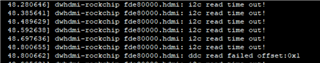
There is an "DDC read failed" when TMDS181 at SRC configuration. From customer schematic, this circuit can be configured as SNK side and SRC side.

The sch: HDMI Re-timer 线路12.24.pdf

Test summary:

  1.  Attach R740/R744, configured as SNK, the device work well.
  2.  Detach R740/R744 and attach R741/R745, configured as SRC (but I checked with customer, the pull up resistor R411/R408 is detached, which is different with datasheet figure.32). the product shows DDC read failed.
  3.  Then detach R741/R745 and attach R740/R744 to set to SNK again, still shown DDC read failed issue.
  4.  Replace a new TMDS181 and attach R740/R744, configured as SNK, the device work well.

Questions and support need:

1) According to test 3 and 4, it seems that the device is failed after setting to SRC without pull up resistor. Is this pull up resistor the root cause? If it might be, could you please help to explain the reason? If not, could you please help to provide some suggestions or any potential reason for this issue?

2) Except the pull up resistor, is there any other circuit need be modified in this schematic when change from SNK to SRC?

3) How to fix the board which failed in test 2? Do you have any insights?

I will keep following the debug progress and post to you when there is any update. Thanks!

BRs,

Rannie

  • Rannie

    1. TMDS181 implements DDC clock stretching, please check and make sure the source can support clock stretching. The DDC read will not work if the source does not support clock stretching. In this case, they will have to use the external I2C level shifter

    2. TMDS181 and TCA9517 do not have internal pullup resistors, so you would need to populate R408 and R411. Does the DDC read work if they populate R408/R411 and the source supporting clock stretching? Please make sure to de-populate R742 and R746 as well

    3. For #3, please remove R740 and R744, please remove the resistor and install two brand new 0ohm resistors. This behavior is not expected and I want to make sure it is not a board rework issue.

    Thanks

    David

  • Hi David,

    Thanks for your reply.

    Per talked:

    • Customer use RK3588, which can't support clock stretching. So, they should use the existing implement in their schematic. If they set to use SCL_SRC/SDA_SRC, the DCC read will fail.
    • For the #3, change the resistor will not damage the chip.
    • TI recommend customer always use existing implement whether the CPU support clock stretching or not.

    BRs,

    Rannie

  • Hi David,

    Another question I would like to double check with you:

    When they configure the board to SRC side application and connect it to a CPU without clock stretching, whether the device be damaged?

    BRs,

    Rannie

  • Rannie

    I do not expect the unit be damaged if it is connected to a CPU without clock stretching. Clock stretching is a functional issue, device damage is an electrical issue, these two are not related to each other.

    Thanks

    David

  • Hi David,

    Thanks for your confirmation!

    After checking with customer, actually they connect the SRC Pin to GND in SRC side application and then the issue happened, and the device seems failed.

    Detach R740/R744 and attach R741/R745, configured as SRC (but I checked with customer, the pull up resistor R411/R408 is detached, which is different with datasheet figure.32). the product shows DDC read failed.

    R742 and R746 is attached (SRC is connected to GND) in this test.

    Could you please help to answer below question?

    What is the impact for TMDS181 of source side I2C grounding (what customer do in their test) in the SRC side application?

    BRs,

    Rannie

  • Rannie

    If they are connecting the TMDS181 SDA_SRC and SCL_SRC to the SoC, then they have to remove the pulldown resistor. Connecting the SDA_SRC and SCL_SRC to the SoC with the pulldown resistor is not an implementation supported by TMDS181 so I honestly don't know what will happen to the SDA_SRC and SCL_SRC pin. Please work with our quality team to start a FA process on this unit.

    Thanks

    David