


Part Number: SN65LVDS31
Tool/software:
Hello Team
I have a simulation box to test my DUT and the interface between simulation box and the DUT is SPI.
Simulation Box is the SPI Slave, and the DUT is SPI Master
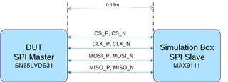
The SPI is transmitted over LVDS and the driver used in Master side is SN65LVDS31 whereas in the receiver side driver is MAX9111. Please find below the illustration of the same. `The length of the cable between the DUT and the slave is 0.18m.
The harness connecting between DUT and Simulation box was modified with a relay switch in between as shown below. All the lines are now passed via SPST Relay with on state resistance of 0.4 ohms. The relay is used to isolate the DUT from the simulation box as shown below
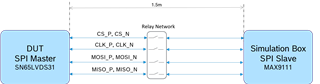
With this change the length between master and slave is increased by 1.5m. With this new change there is a signal integrity observed in the SPI lines sporadically. Could you please let me know the design recommendation for SPI.
Is the additional length creating an issue here. If so, what is the maximum length we can route the LVDS Lines.
Awaiting your reply
