DP83825I: How to bring up DP83825 by our linux code

Part Number: DP83825I

Tool/software:

Hi team,

Could you help to explain how we can bring up device by our Linux code?

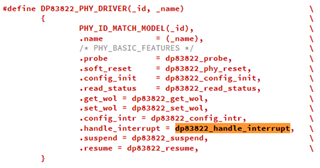
dp83822.c « phy « net « drivers - kernel/git/stable/linux.git - Linux kernel stable tree

1. While initial status, which command we need to run first?

dp83822_of_init or dp8382x_config_init

2. What's register we need to modify in init code?

Thanks,

Leo

  • Dear Sir

    We are using LWIP on the STM32H7R7L8H6H platform with the DP83825 PHY. However, we only have the initialization code for the DP83848, and not for the DP83825. As a result, the device is not able to ping, and we need to know how to initialize the DP83825.

    I have printed the registers of the DP83825. Could you please confirm if the DP83825 is working correctly now? Alternatively, could you provide any debugging directions to help us understand why the device is still not able to ping?

    ** Print ETH Reg Start **
    ** Reg =0x00 Value = 0x3100 **
    ** Reg =0x01 Value = 0x786d **
    ** Reg =0x02 Value = 0x2000 **
    ** Reg =0x03 Value = 0xa140 **
    ** Reg =0x04 Value = 0x01e1 **
    ** Reg =0x05 Value = 0xc1e1 **
    ** Reg =0x06 Value = 0x000d **
    ** Reg =0x07 Value = 0x2001 **
    ** Reg =0x08 Value = 0x0000 **
    ** Reg =0x09 Value = 0x0000 **
    ** Reg =0x0a Value = 0x0100 **
    ** Reg =0x0b Value = 0x0000 **
    ** Reg =0x0c Value = 0x0000 **
    ** Reg =0x0d Value = 0x0000 **
    ** Reg =0x0e Value = 0x0000 **
    ** Reg =0x0f Value = 0x0000 **
    ** Reg =0x10 Value = 0x0615 **
    ** Reg =0x11 Value = 0x0108 **
    ** Reg =0x12 Value = 0x0000 **
    ** Reg =0x13 Value = 0x0000 **
    ** Reg =0x17 Value = 0x0065 **
    ** Reg =0x19 Value = 0x8c00 **
    ** Reg =0x1f Value = 0x0000 **
    ** Reg =0x4a0 Value = 0xffff **

  • Hi David/Leo, 

    I can see that you are repurposing the DP83822 driver for this application with the DP83825. Is this register dump after the driver is loaded?

    I also wanted to understand the setup being used here a bit better. What xMII interface is being used? What is the link partner in this setup? 

    One thing I noticed from the register dump is the FIFO underflow flag. This usually points towards a ppm mismatch between the clocks. This can be checked by measuring the TX_CLK and the PHYs RX_CLK. These should be within 100ppm of each other at most. 

    Best,

    Vivaan

  • Hi Vivaan

    Thanks for your reply.
    The register dump is after driver loaded, and the init code is under below.

    Fullscreen
    1
    2
    3
    4
    5
    6
    7
    8
    9
    10
    11
    12
    13
    14
    15
    16
    17
    18
    19
    20
    21
    int32_t DP83848_Init(dp83848_Object_t *pObj)
    {
    uint32_t regvalue = 0, addr = 0;
    int32_t status = DP83848_STATUS_OK;
    uint32_t phyID, regValue;
    //phy address = 0
    pObj->IO.ReadReg(0x0, 0x02, &regvalue); //PHY_ID1_REG
    phyID = regvalue << 16;
    pObj->IO.ReadReg(0x0, 0x03, &regvalue); //PHY_ID2_REG
    phyID = (phyID | (regValue));
    /* Reset PHY. */
    status = pObj->IO.WriteReg(0x0, DP83848_BCR, 0x8000); //DP83848_BCR is 0x0
    if (status == 0)
    {
    status = pObj->IO.ReadReg(0x0, 0x01, &regValue );
    /* RMII configuration */
    status = pObj->IO.ReadReg(0x0, 0x17, &regValue );
    //status = pObj->IO.WriteReg(0x0, 0x17, 0x80| 0x1 );
    XXXXXXXXXXXXXXXXXXXXXXXXXXXXXXXXXXXXXXXXXXXXXXXXXX

    I am using a laptop with a 10/100M/1G network card and have set a static IP (192.168.1.100). The DP83825 is configured in RMII mode with DHCP disabled, IP address 192.168.1.101, netmask 255.255.255.0, and gateway 192.168.1.100.

    And I am using a 25Mhz xtal conect to XI pin, therefore the DP83825 is running on master mode, it will output 50Mhz to RMII_REF_CLK

  • Hi Vivaan

    Do uou mean the register RCSR Register(0x17) = 0x65, it seems is RMII_Overflow_Status Flag.

  • Hi Vivaan,

    DP83825 does not have TX_CLK and RX_CLK output pins for measurement. Which signal pin can I measure instead of TX/RX_CLK? In addition, the input clock 25MHz has a tolerance of less than ±100 ppm. See pic

  • Hi, 

    Thank you for all the clarifying information about the setup.

    The initialization code looks to be fine.

    Do uou mean the register RCSR Register(0x17) = 0x65, it seems is RMII_Overflow_Status Flag.

    Yes, I am talking about register 0x17. There is an error in this register. The bits for overflow/underflow should be flipped to show that 0x1 is under/overflow while 0x0 is normal operation. This change has been noted and will be fixed in the upcoming datasheet revision by next week. Based on this, we can conclude that the device is experiencing underflow, not overflow. 

    I believe the cause of the issue are the resistors R98, R101 and R102. These resistors are used as a way to enact a loopback, and should not be used for normal operation. I would recommend that you try testing again with these resistors removed. If that, for whatever reason, does not fix this behaviour, I would like to take the following debug steps.

    Since the PHY is set to RMII Master Mode, I want to double check some things that may be the cause of this behaviour.

    First, I wanted to verify that the input clock meets the following requirements, as laid out in the datasheet. I was not able to find the exact crystal used in the schematic so I ask for you to kindly verify that these requirements are met. 

    Second, I wanted to verify the 50MHz output clock. Can you measure this clock at the MAC interface input and make sure that the ppm is under the limit expected by the MAC? A good resource for this would be this FAQ explaining the ppm differences. For this application, I believe RMII config #1 example best describes the situation. 

    Best,

    Vivaan

  • Hi Vivaan

    Thanks for your great help.

    after check the loopback test resault, the problem is come form the STM32 MCU side, and after modify the MPU setting of STM32 MCU.

    we can bring up the DP83825.

    Thanks again.

  • Hi Vivaan,

    What's the register setting to complete IEEE Ethernet Compliance Tests?

    Thanks,

    Leo

  • Hi Leo, 

    The following two documents should have all the information to complete the IEEE compliance tests

    https://www.ti.com/lit/an/snla385/snla385.pdf?ts=1738870487769&ref_url=https%253A%252F%252Fwww.ti.com%252Fproduct%252FDP83825I 

    Section 5 of this above document details the register settings for different tests

    https://www.ti.com/lit/an/snla266a/snla266a.pdf?ts=1738870486977&ref_url=https%253A%252F%252Fwww.ti.com%252Fproduct%252FDP83825I 

    Let me know if there are any questions.

    Best,

    Vivaan