This thread has been locked.

If you have a related question, please click the "Ask a related question" button in the top right corner. The newly created question will be automatically linked to this question.

TMDS1204: ESD serial resistor

Part Number: TMDS1204
Other Parts Discussed in Thread: STRIKE, TDP2004

Tool/software:

I am going to use TMDS1204 for my project and saw a recommendation in the datasheet for using serial resistors on the hi-speed lanes as additional protection related with ESD TVS diodes.

Let me introduce my understanding please let me know if i miss something:

a. Any additional serial components on the hi-speed traces are sources of unmatched impedance and kind of source of reflection, which should increase return losses and insertion losses.

b. More popular level of ESD protection is IEC 61000-4-2, level 4. 15kV/8kV
During the ESD event even with ESD TVS diodes, there will be some overvoltage impulse as mentioned in the datasheet "A clamp voltage greater than 4.3V will require a RESD on each high-speed differential pin." 
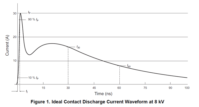
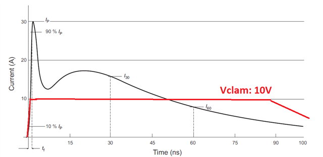
Based on my understanding TVS diodes cut the initial ESD impulse down to Vclamp (Vsnapback) and since the voltage source (ESD) is still the same than a duration of the overvoltage impulse (after TVS) sould be the same as the duration of the ESD initial impulse. 

c. TMDS1204 has its own ESD protection "Human-body model (HBM)"  up to 4kV, as I remember HBM model has a similar time domain of the ESD events, and since point "b", looks like internal ESD HBM protection should be enough for protect by Vclamp (Vsnapback)

So let me ask:

1. Do you have any estimation of how serial resistors (0402) affect the hi-speed signal integrity?

2. Could you please clarify the benefits of using serial resistors here?

3. There are in the datasheet:
"It is recommended that the ESD protection component has a breakdown voltage of ≥4.5V and a clampvoltage of ≤4.3V. A clamp voltage greater than 4.3V will require a RESD on each high-speed differential pin."
and the recommendation to use PUSB3FR4.
The last one is a snapback device, and as I can see that has Vclamp 4V (for 7A) and  Vbreakdown 9V (typ). 
Is my understanding correct that using PUSB3FR4 excludes the need to use ESD serial resistors?

Thank you!

  • Hi,

    a. Any additional serial components on the hi-speed traces are sources of unmatched impedance and kind of source of reflection, which should increase return losses and insertion losses.

    Correct, so we typically recommend the Resd to be 1 or 2 ohm to minimize the return loss and insertion loss impact.

    c. TMDS1204 has its own ESD protection "Human-body model (HBM)"  up to 4kV, as I remember HBM model has a similar time domain of the ESD events, and since point "b", looks like internal ESD HBM protection should be enough for protect by Vclamp (Vsnapback)

    No, the HBM and IEC 61000-4-2 are two different standards. HBM and CDM we listed in the TMDS1204 datasheet are intended to ensure the IC survives the manufacturing process. HBM is usually sufficient for controlled environments but it is inadequate for system level testing. The system level testing required is the IEC 610000-4-2 which is more stringent than HBM. The main difference between the two are:

    • The amount of current released during a strike
    • The rise time of the voltage strike
    • The number of voltage strikes repeated in the test 

    For the IEC 61000-4-2, there are four levels with 2kV, 4kV, 6kV, and 8kV. With the IEC61000-4-2 being a system level testing, an overall system level ESD protection solution is required. Since we have no control over the specific IEC level requirement, or the ESD protection diode being selected, we put in the datasheet the Resd recommendation. Besides the ESD protection diode, the role of Resd is to limit the amount of ESD currents to provide an extra level of ESD protection. So besides the ESD protection diode, the customer can tune the Resd in order to meet:

    • Specific IEC level requirement
    • Able to pass HDMI TX and RX electrical compliance requirement
    • Able to pass the HDMI functional testing

    Thanks

    David

  • Hi David, thank you for the comments.

    Don't get me wrong, exactly that advice about serial resistors confused me because I cannot recall that I have ever seen that kind of advice for hi-speed lanes of re-driver, e.g. TI's DS280xxxx, DS280xxxx, DS125xxxx, TDP2004xxxx. Especially the last one, it's a pretty new component, and I have EVB with no serial resistors.

    So, I am just trying to understand if TMDS1204 has specific internal circuits or the recomendation is just another approach to writing of the documentation. Because I don't what increase losses without a strong reason. Honestly, I don't know how much losses can come from the serial resistors and maybe I can ignore it, so it's why I asked about TI's estimation as well.

    Let me ask another way.

    Almost any ESD TVS diode limits voltage impulse a lot. If we have 8 kV (IEC-61000-4-2) on a connector, "after" ESD VTS the voltage pulse will be... let's say no more 10V for most cases during all time. IEC-61000-4-2 define 

    Following IEC61000-4-2 the time domain (I see it's current not voltage):

    So, then we can say that ICE-61000-4-2, 8 kV impulse has a similar duration, but the voltage is limited by TVS. Let me very schematically draw a voltage line (for no snapback device) on top of a current line:

    I suppose internal ESD HBM protection of the TMDS is also kind of TVS. I understand that two parallel TVS with no resistance between them don't work as separate devices. But, for such a fast-rise edge (ESD pulse), an inductivity is probably even more resistant than 0R...2R resistor. Maybe the final max voltage on the pins of the re-driver is bigger than 10V, but I am pretty sure it's much more smaller than 500V defined by HBM.

    So in my mind looks like, internal ESD HBM protection should be enough to block the rest of ESD impulse energy "after" any HI-speed TVS that I know.
    It's the reason why 
    I don't understand and ask about "It is recommended that the ESD protection component has a breakdown voltage of ≥4.5V and a clampvoltage of ≤4.3V. A clamp voltage greater than 4.3V will require a RESD on each high-speed differential pin"

    Please let me know if I miss something. 

  • Hi,

    The issue here is that we have no control over the ESD protection diode selection, the ESD layout design, or the actual ESD event, etc., as it is a system level design and event. But at the same time, we need to ensure that the TMDS1204 itself is not going to get damaged from the ESD strike. For example, if someone picks an ESD protection diode with clamping voltage of 12V and the ESD event is at 10V, that ESD protection diode will not clamp and present a low impedance path to shunt the Iesd to GND. In this case, the 10V ESD will present to the TMDS1204 output. The HBM and CDM we listed in the TMDS1204 datasheet are intended to ensure the IC survives the manufacturing process, HBM is usually sufficient for controlled environments but it is inadequate for system level testing. The TMDS1204 output I/O is also not designed to withstand the 10V ESD strike, so most likely the TMDS1204 IC will get damaged from this particular ESD strike. 

    So we put in the TMDS1204 datasheet the recommendation of "It is recommended that the ESD protection component has a breakdown voltage of ≥4.5V and a clamp voltage of ≤4.3V" as a way to bound the ESD protection diode selection. And for "A clamp voltage greater than 4.3V will require a RESD on each high-speed differential pin" is to ensure the TMDS1204 output I/O will not get damaged from an ESD strike of less than 4.3V with the Resd providing the majority of ESD protection in this case. 

    You are correct that the Resd will present additional insertion loss and return loss, so the recommended Resd is 1 or 2ohm to minimize the insertion and return loss as much as possible. The selection of Resd is such that:

    • Meet the specific IEC level requirement
    • Able to pass HDMI TX and RX electrical compliance requirement
    • Able to pass the HDMI functional testing

    Thanks

    David


  • Hi David, thank you for the fast respond!

    I use TMDS1204, DS280MB810, TDP2004 in my system, so does your coments mean this requirement is a specific requirement for TMDS1204 only from that list? 

  • Hi,

    Different devices are going to have different process and ESD design structure, so the recommendation in the TMDS1204 datasheet is specific for TMDS1204.

    Thanks

    David 

  • Hi David, ok I see, thank you!

    I'll make some calculations and probably return with questions in a couple of days. Please keep the thread open yet. 

    Appreciate your service.

  • Does TI have any material where I could find any simulation/estimation for return losses for 0 Ohm resistors or anything similar? 

  • Hi,

    We don't, but typically for high speed signal, we would recommend to use size 201 for the capacitor and the resistor.

    Thanks

    David