Other Parts Discussed in Thread: TUSB1004, TUSB1104, STRIKE, TUSB522P, TUSB521Q1-EVM, TUSB1002A
Tool/software:
Hello,
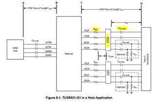
for implementing the TUSB521 I study the schematic on page 22 of the datasheet. See Figure 8-1.
I noticed that after the chip the first Part is the R ESD then the ESD diode and direct on the connector comes at final the AC-coupling capacitor. Is this really right?
In chapter 8.2.2.3 ESD Protection the datasheet says “Place the ESD component near the USB connector.”
In my opinion the AC-Coupling capacitor should be the first part after the TUSB521. Only than it is possible that the ESD diode is near es possible to the connector.
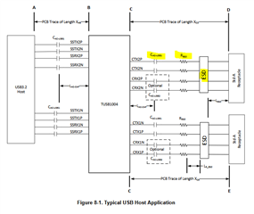
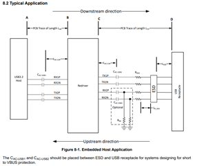
In other datasheets from TUSB522, TUSB1004, TUSB1104 and so on, is it in this way.
1. What is the right sequence of the parts and why?
2. Is the ESD series resistant for an USB-C design really necessary?
Thaks!
Markus