This thread has been locked.

If you have a related question, please click the "Ask a related question" button in the top right corner. The newly created question will be automatically linked to this question.

DS90UB953-Q1: I2C lock-out issue

Part Number: DS90UB953-Q1

Tool/software:

Dear all,

I have a question regarding the I2C transceiver of the DS90UB953-Q1 serializer. Sometimes no I2C transactions are propagated over the back channel for some time after our initialization. We use a combination of DS90UB954 (deserializer) and DS90UB953-Q1 (serializer).

On the sensor side, where the serializer is located, the serializer IC is powered on (by the +1V8 supply) before the other peripherals (image sensor, EEPROM and 2 ambient light sensors) are powered (by a switchable +3V3 supply, which is enabled by a GPIO pin of the serializer). We do this because we use 2 ambient light sensors in combination with our image sensor, one of which needs to have a different I2C address set. The method of settings a different I2C address for the ambient light sensor is to power on the sensor while an IO pin of the sensor is HIGH. Because not all devices are +1V8 I2C compatible, the I2C bus operates at +3V3 and becomes live at the same time the +3V3 supply is switched on (±100 ms after powering the serializer). This yields weird behavior were sometimes no I2C propagation is possible for >1000ms.

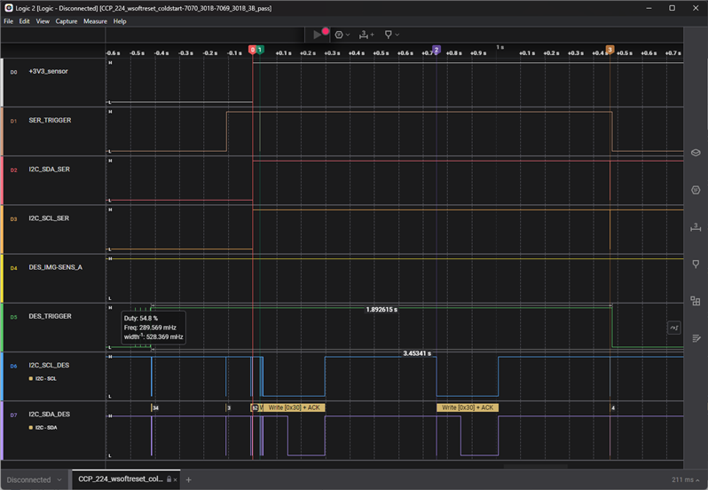
Log of serializer and deserializer I2C busses with markers:

0 = turn-on +3V3
1 = first attempt to write to 0x30
2 = second attempt to write to 0x30
3 = third and successful attempt to write to 0x30. (First message propagated over Serializer bus)

We've already checked and tried the following:

- Dips in DS90UB953 power supply and PGOOD (Non visible)
- Strapping voltage IDX pin (Was as expected for 3V3 i2c w address 0x19)
- Soft reset of DS90UB953 directly after enabling the 3V3 supply (by writing 0x01 to register 0x01 of DS90UB953)

Can anybody tell us, why sometimes the I2C bus is locked for >1000ms and other times immediately propagates messages from the back-channel without issues.

Kind regards,


Our register settings are:

# Define I2C adresses (7-bit adressing
# The device ID is the physical I2C adres
# The alias is the virtual I2C adres
# The deserializer only propagates I2C communication if the adres in the message matches an address present in the alias ID registers
# It is possible to set a different alias. The deserializer translates the virtual address to the physical address.
# 954 Device ID
UB954="0x3D"
# 953 Device ID
UB953ID="0x19"
# 953 SER Alias  
UB953="0x0C"
# Sensor ID
AR0234ID="0x10"
# Sensor Alias
AR0234="0x10"
# EEPROM ID
EEPROMID="0x50"
# EEPROM Alias
EEPROM="0x50"
# Ambient light sensor A ID
VD6238TXAID="0x20"
# Ambient light sensor A Alias
VD6238TXA="0x20"
# Ambient light sensor B ID
VD6238TXBID="0x30"
# Ambient light sensor B Alias
VD6238TXB="0x30"

# Function wrapper for writing and reading i2C commands
WriteI2C () {
# $1=device $2=reg $3=val
  i2cset -y 1 $1 $2 $3  
}
ReadI2C () {
# $1=device $2=reg $3=number of reg
  i2cget -y 1 $1 $2 i $3  
}

######################
# Setup communication
######################

# Disable port 1
WriteI2C $UB954 0x0C 0xC1
# Address port0 and enable write to registers
WriteI2C $UB954 0x4C 0x01
# Set backchannel configuration
# BC always on, I2C passthrough, CRC enable and 50Mbps
WriteI2C $UB954 0x58 0x5E
# set serializer i2c alias
WriteI2C $UB954 0x5C $(( UB953 << 1 ))

############################
# Configure I2C peripherials
############################

# Write physical address of AR0234 in TargetID[0] register
WriteI2C $UB954 0x5D $(( AR0234ID << 1 ))
# Write alias address of AR0234 in TargetAlias[0] register
WriteI2C $UB954 0x65 $(( AR0234 << 1 ))
# Write physical address of 24AA025 in TargetID[1] register
WriteI2C $UB954 0x5E $(( EEPROMID << 1 ))
# Write alias address of 24AA025 in TargetAlias[1] register
WriteI2C $UB954 0x66 $(( EEPROM << 1 ))
# Write physical address of VD6238TXA in TargetID[2] register
WriteI2C $UB954 0x5F $(( VD6238TXAID << 1 ))
# Write alias address of VD6238TXA in TargetAlias[2] register
WriteI2C $UB954 0x67 $(( VD6238TXA << 1 ))
# Write physical address of VD6238TXB in TargetID[3] register
WriteI2C $UB954 0x60 $(( VD6238TXBID << 1 ))
# Write alias address of VD6238TXB in TargetAlias[3] register
WriteI2C $UB954 0x68 $(( VD6238TXB << 1 ))

###################
# Setup serializer
###################

# Set I2C speed serializer (SCL_HIGH_TIME) to Fast
WriteI2C $UB953 0x0B 0x13
# Set I2C speed serializer (SCL_LOW_TIME) to Fast
WriteI2C $UB953 0x0C 0x26

# GPIO2_ser (=TRIGGER_3V3) and GPIO3_ser(=IMG-SENS_EN) are set to output
WriteI2C $UB953 0x0E 0xC3
# GPIO0 is propagated over Forward Channel w CRC
WriteI2C $UB953 0x33 0x05
# Enable RMTEN as input source for GPIO2_ser and GPIO3_ser
WriteI2C $UB953 0x0D 0xC0

#####################
# Setup deserializer
#####################

# GPIO0_des & GPIO1_des is set to output
WriteI2C $UB954 0x0F 0x7C
# GPIO0_des output is enabled with src being GPIO0_ser (=FLASH) input
WriteI2C $UB954 0x10 0x01
# GPIO1_des output is enabled with src being local I2C register and value of local I2C register is high
# for logic LOW write value: 0x11, for logic HIGH write value 0x13
# logic LOW = PoC On, # logic HIGH is PoC Off
WriteI2C $UB954 0x11 0x11
# [GPIO3_ser_src [4] = GPIO2_des (IMG_SENS-a) GPIO2_ser_src[4] = GPIO1_des (TRIGGER)]
WriteI2C $UB954 0x6F 0x21
# [GPIO1_ser_src [4] = constant 0 GPIO0_ser_src[4] = 0]
WriteI2C $UB954 0x6E 0x89

########################
# Configure videostream
########################

# set CSI transmit enable
WriteI2C $UB954 0x33 0x01
# enable forwarding of video data from port0 to CSI transmitter
WriteI2C $UB954 0x20 0x20