Part Number: THVD8010
Other Parts Discussed in Thread: THVD8000
Tool/software:
Hi Team,
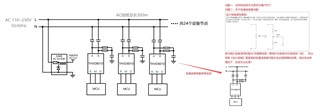
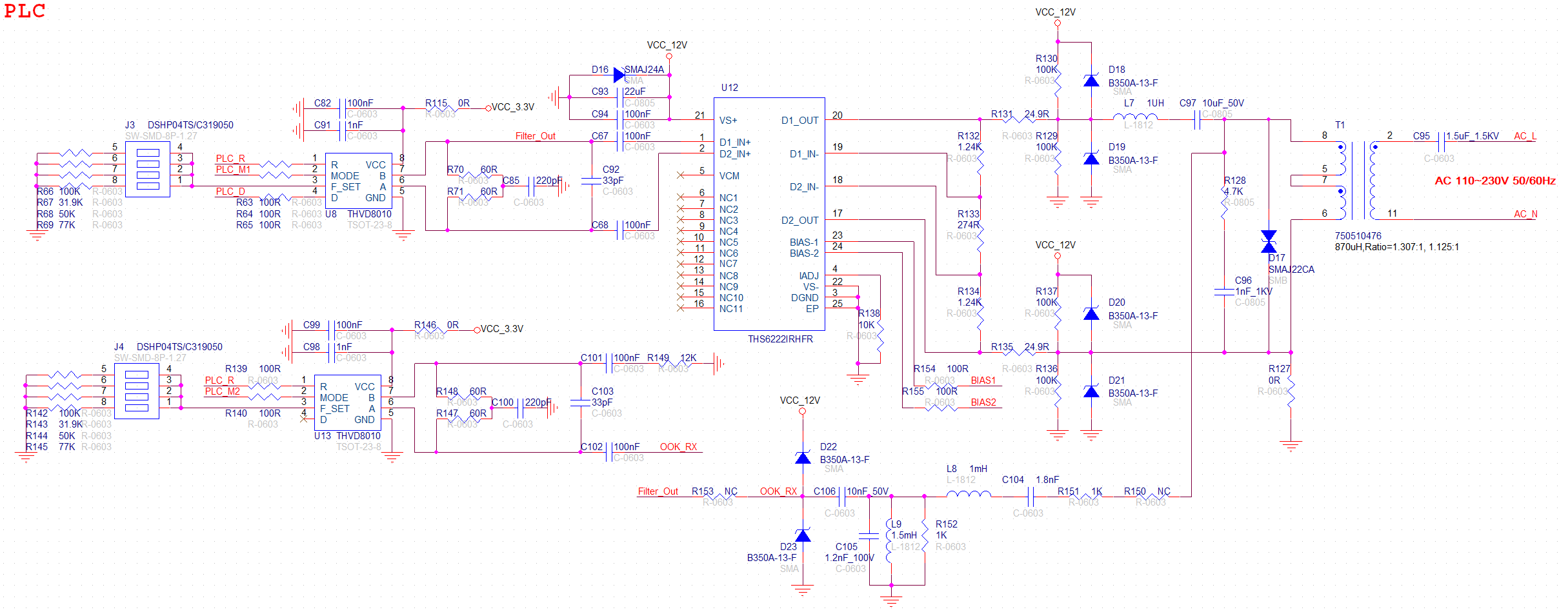
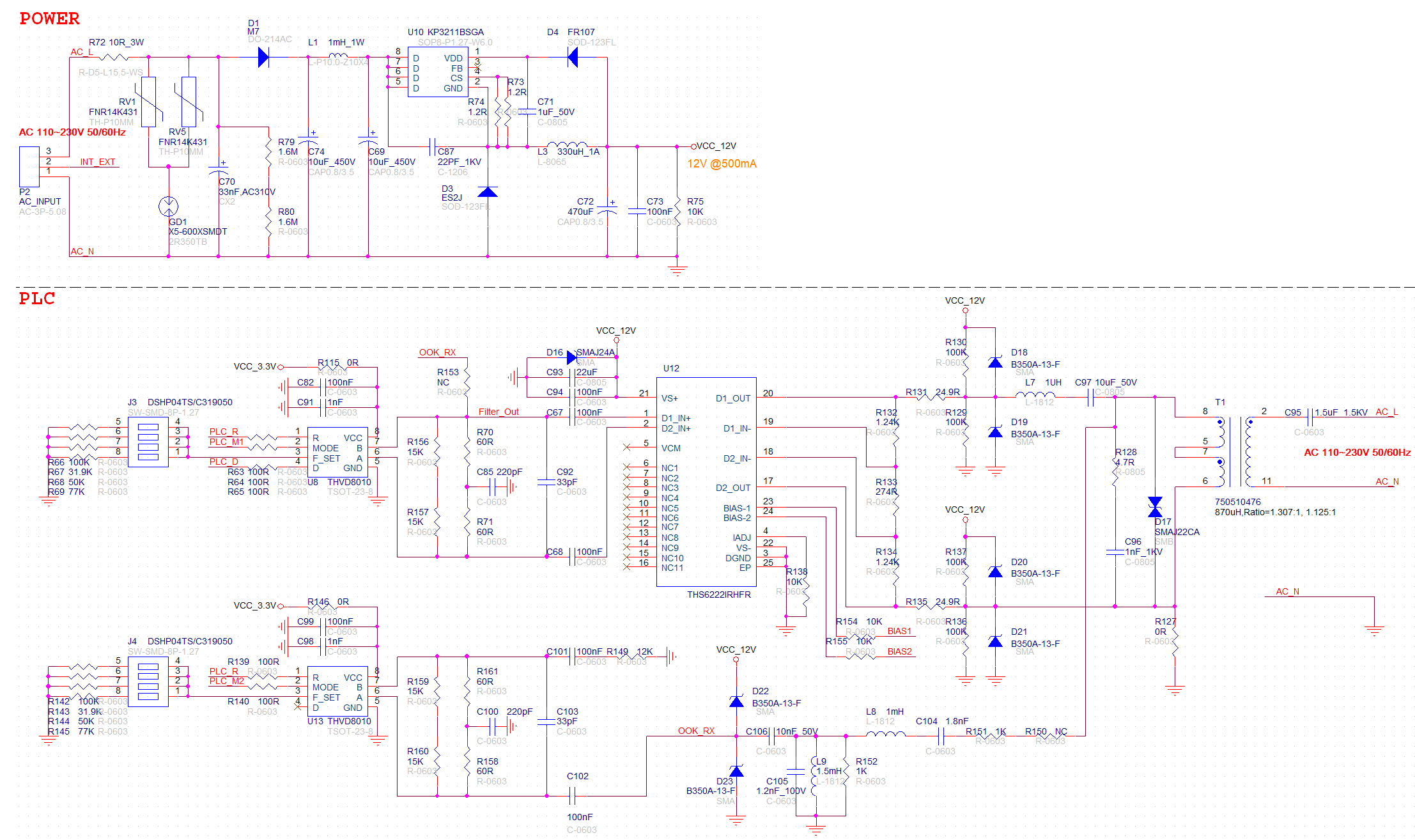
1. Is the application method shown in the following figure correct?(total 24 nodes)
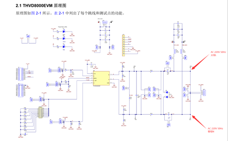
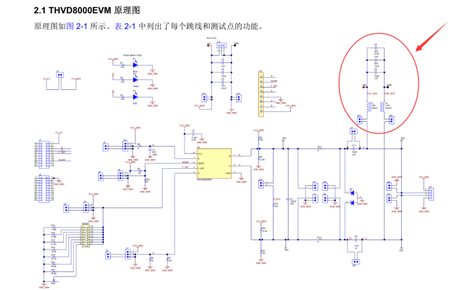
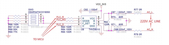
2. Regarding the issue of low-pass filters, please provide an answer based on the schematic diagram.
The device is using an AC non isolated power supply (N line connected to GND), and the low-pass filter may not achieve the expected effect. What should be done in this case?