TCA9800: TCA9800 connection RILC (Low-level allowed pull-down resistance)

Part Number: TCA9800
Other Parts Discussed in Thread: TCA9509, LSF0002, LSF0102, PCA9515A, TCA9803, TCA9517, TCA39306, TCA9517A, TCA9617B

Tool/software:

Hello Team,

I have to interface a 1.8V I2C master  board (new board) with 2 existing  3.3V board (not in the same time) :

 - one board with a FET based I2C transceiver.

 - one board with a  voltage offset I2C transceiver

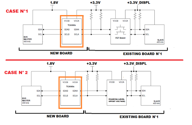
Following the datasheet, the A side should be connected to the existing board because of the pullup resistors on the existing boards.

The master (1.8V) should connected to the B side.

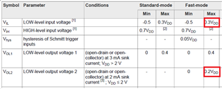
The master is compliant with I2C standard:

VIL max <0.3VDD =0.3x1.8 = 0.54V

VIH min > 0.7VDD=0.7x1.8 = 1.26V

VOL < 0.2VDD@2mA = 0.36V@2mA

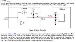
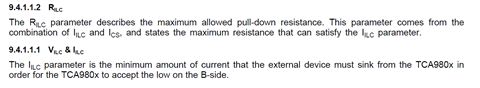
From the TCA980x datasheet,  VIL, VOL are compatible with the master specifications. But there is is an issue with RILC (Low-level allowed pull-down resistance).

The maximum value should be 150ohms, whereas with my I2C compliant master, the RPD=Vol/Iol= 0.36/2mA=180ohm > RILC 

I understand that this value is important for bus contention situations. but in which case "bus contention" can occur? Arbitration,?

Have you an idea to resolve my issue?

Best Regards.

Sylvain

  • Hi Sylvain,

    (Edited 1/23/25)

    "This design won't be compatible with the datasheet RILC requirement."

    The concern with the IEXT is that we do not want additional current to contribute to the external current being sunk into the device on B-side:

    This helps to ensure proper functionality of the device.

    Regards,

    Jack

  • Hello Jack,

    Sorry, but I don t understand your answer:

    - In the datasheet, there is mentioned that RILC comes from ILC and not IEXT.

    - The ILC parameter is used to ensure  a low level on B side. => So I understand that if I don't respect the RILC, the low level on B side of the TCA980x will not be seen.

      May you help me to understand?

    Sylvain

  • Hi Sylvain,

    You are correct here- the reference I made in my previous response is relevant to external pullups only and is not influenced by the external NMOS driver. Is it possible to increase the VDD of your external driver to >2V? This would effectively make the impedance <150ohms and in-line to the Rpd requirement in the datasheet. 

    Since the device supports VCCA> VCCB operation, swapping the I2C Master onto A side will remove this requirement as the IILC/RILC is only on B-side. Otherwise, there are other I2C buffers with less restrictions such as the TCA9509 that has the voltage offset on A-side. 

    Regards,

    Jack

  • Hello Jack,
    Thank you.
    Please find below my answers:
    -No it's not possible to increase the "+1.8V" voltage on the B side of the TCA980X. This voltage is imposed by the I2C master.


    - According to 10.1.2.1 paragraph, I shouldn't swapp the transceiver with I2C master on A side, because there is Fet based transceiver on the existing board (CASE N°1) that requires pullup resistor on the bus.


    - TCA9509 is not adapted to our design because I need a low power IC. (the quiescent current should less a few µA when one of the two power supply is switched off). The TCA9509 is not specified in this condition. Morevover Vol is specified at a very current (20µA on side A).

    Regards.

    Sylvain

  • If you need only level shifting but not buffering, use another FET-based shifter like the LSF0102 or LSF0002. (Note that all three sets of pull-up resistors then act in parallel; check the drive strength of your 1.8 V device(s).)

  • Hello Clemens,

    Thank you for your proposal but I think there's a problem:

    The problem with FET based shifter is that it can't cancel the offset voltage introduced by the PCA9515A :
    The VOL PCA9515A is  0.6V (max)  which will be  transmitted by the  FET based shifter on the +1.8V side. The I2C master VIL (0.3*1.8=0.54V) is lower than PCA9515A  VOL .==>  VOL(PCA9515A) > VIL (I2C MASTER ).

    Regards

  • Hi Sylvain,

    Any particular reason why the FET based I2C translator and static voltage offset buffer is being used here if not translation is being used? Is it for isolation purposes between the 3.3V nodes? 

    Regards,

    Jack 

  • Hi Jack,

    Yes, FET based I2C translator and static voltage offset are used for isolation purpose (+3.3V  and +3.3V_DISPL power supply power domain). Modifications to the 2 existing boards are not allowed.

    Regards

    Sylvain

  • Hi Sylvain,

    I understand that this value is important for bus contention situations. but in which case "bus contention" can occur? Arbitration,?

    Arbitration in multi-master environments yes. But I think the datasheet most commonly refers to the ACK/NACK related clock period. This would be the case where the master device would be reading data from the target device. The target device would be sending its data on SDA from SDAA to SDAB. When the master needs to ACK, it must have an RILC pull down value <150 ohm to ensure that the ACK bit is sent properly from B-side to A-side during the 9th clock transition. I believe this is why the 150 ohm requirement is listed in the datasheet. 

    For incorrect configurations like the one shown in figure 17, it is incorrect because the TCA9517 always outputs a voltage ~ 0.52V. Since the current it is sinking is ~ 1 mA due to internal current source of TCA9803, the rough calculation for RILC becomes 0.52V / 0.001 A = 520 ohm >> 150 ohm requirement. 

    The key problem is that your master device from a datasheet perspective does not have the drive strength requirement of < 150 ohm RILC based off the following table: 

    At VDD = 1.8V, VOL2 = 0.2 x 1.8V = 0.36V. This is measured when Isink = 2mA, thus RILC = 0.36V / 2 mA = 180 ohm. 

    My question is do we have VOL2 output voltage data for the master when the Isink is 1 mA? The requirement for IILC of the TCA9803 is 1 mA (from the internal current source). 

    Say for instance that for VDD <= 2V, @ 1mA sink current, VOL = 0.15V max, then RILC becomes RILC = 0.15 V / 0.001 A = 150 ohm. Are we certain that at 1 mA current sink the VOL2 > 0.15 V? 

    FYI, I am back in office now. I will take a look at the ICCQ current testing soon either today or tomorrow. 

    Regards,

    Tyler

  • Hello Tyler,

    The master is not specified at 1mA. The only information given in its data sheet is: “The I2C is designed to be compatible with the I2C Bus Specification”. That's why I shared with you the table with Vol2 (taken from the NXP I2C specifications UM10204).

    Remark: it 's not necessary to do ICC measurements if the IC could'nt no be used in my design.

    Regards.

    Sylvain

  • Hi Sylvain,

    At this point, I can't 100% confirm that the PD resistance is enough to satisfy the RILC requirement based off the table that you gave for the master PD strength. So from a datasheet perspective I would have to say that TCA9803 may not be compatible with your design since 180 ohms > 150 ohms. 

    Is buffering absolutely required here? What is the need for the PCA9515A? It seems this device is preventing the design from using TCA39306 to convert 3.3V to 1.8V. 

    Regards,

    Tyler

  • H Tyler,

    Thanks you for your feedback.

    The PCA9515A is mounted on an existing board and  my new design should  be compliant with this existing board. It's not possible de to modify it.

    The main problem is that PCA9515A on the existing board introduces an offset (Vol@10µA or 6mA: 0.6V). 

    If I use a "passive" level translators on the board, this offset is  transmitted to the +1.8V side.

    The I2C master VIL (0.3*1.8=0.54V) :    VOL [PCA9515A@3.3V] > VIL [master@1.8V]   => KO!!!

    That's why I tried to use a buffer, but it's not mandatory if you have another solution Relaxed....

    To sum up, the need is :

    - adapt a 1.8V I2C master  level  from a new board with 2 existing  3.3V I2C levels board (not in the same time) : one board  is based on a FET-based I2C transceiver (case 1) / the second board is based on a voltage-shifting I2C transceiver (case 2).

    - Low power consumption (< ~ a few hundred µA) on the +1.8V side when the 3.3V is switched off.

    Regards

    Sylvain

  • Sylvain,

    For case 1, a level shifter such as TCA39306 should work then. 

    For case 2, I understand the voltage offset is troublesome due to VIL limitations of a 1.8V controller. This means we cannot use a passFET based level translator between the controller and the PCA9515A. 

    Thus we need to use a buffer to adjust the offset voltage. 

    I know you stated that the VOL offset is compatible to the I2C standard, but do we have a datasheet for the controller that you are using? Maybe it has a slightly different drive capability that would work with the TCA9803. 

    The TCA9803 seems to be the only buffer type that would work in this specific scenario. I have checked the other buffers we offer such as TCA9517, TCA9517A, TCA9617B, TCA9509, but all have large offsets or improper buffer configurations that would not work in this design. 

    Can we double check the device characteristics of the controller once more? 

    Regards,

    Tyler

  • Hello Tyler,

    I agree with you... Before posting this topic on the forum, I checked if another TI IC could work in the 2 cases. Unfortunately, none.

    The controler (I2C master) is a SOM based on a IMX 8M Mini processor. The I2C characteristics are: definded as follow:

    That's why I shared with you datas from IC specifications (UM10204).

    Regards

  • Sylvain,

    Thank you for the information. Based off the datasheets alone, I cannot guarantee that the TCA9803 will "always" work in your system across process, voltage, and temperature due to RILC limitation. 

    However, if you wanted to validate the TCA9803 to see if your controller would work (since we don't know the VOL at 1 mA), then you could conduct the testing across the variables you need to see if the TCA9803 is a good and robust solution for your design. 

    This is the best path forward I can think of without going outside the bounds of the datasheets and the I2C standard. 

    Regards,

    Tyler

  • Thank you Tyler,

    But, without the garantee that the TCA98063 always works in my system, I couldn't use this IC.

    Regards

    Sylvain