A related question is a question created from another question. When the related question is created, it will be automatically linked to the original question.
If you have a related question, please click the "Ask a related question" button in the top right corner. The newly created question will be automatically linked to this question.
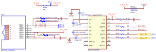
The TRD1+/TRD1− lines are intended to transmit a differential signal. The RX and TX signals are independent, and their signal edges are likely to be coupled as noise into each other. You should transmit RX and TX in separate twisted pairs.
The TTL input DIN2 should not be floating. Please tie this to Vcc with a weak pull up resistor like 20k.
I also usually recommend customers put pull up resistors on the DIN pins that are connected to the MCU and the Rout pins. This ensures the DIN doesn't float when the MCU isn't actively driving the pin (if it's hi-z/tri stated). If the RS232 device is disabled or unpowered, we want Rout to be high if the MCU is on to ensure a glitch doesn't occur on the pin that might look like a start bit.