This thread has been locked.

If you have a related question, please click the "Ask a related question" button in the top right corner. The newly created question will be automatically linked to this question.

THVD1420: rise edge drop issue

Part Number: THVD1420
Other Parts Discussed in Thread: THVD1400, SN65176B

Tool/software:

Hi expert

Now my customer had a new energy project which have opportunity to design in our RS485 and meet some issue.

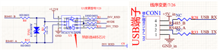
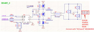
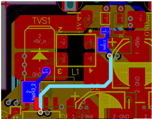
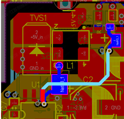
These are the schematic and PCB of customer’s board, there are two positions need 485, one is ” 4G board”, another one is ” power board “.

Customer used NCA3176 at ” 4G board”, and used SN65176 at ” power board “. Now we find there is a voltage drop at the 485 signal rise edge while use ” 4G board” send 485 signal to ” power board “. But there isn’t voltage drop while use ” power board “ send 485 signal to ” 4G board”. The signal rate is about 115200.

We have try these solutions:

  1. Use SN65176BDR to replace NCA3176 at ‘4G board’, it can work and don’t have voltage drop. But the”4G board” is powered by 3.3V, we think SN65176BDR can’t work at this condition. So we want to use THVD1420 to replace NCA3176, but it still have issue.
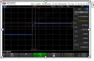
  2. Test the comm voltage wave of RS485A&RS485B to GND based on NCA3176 at ‘4G board’, there isn’t voltage drop.
  3. Use external line to make the line between 2 board short , no improve.
  4. Add 10nF cap with  the TVS2 can help the rise edge smooth, but the rise time increase to 1.4us.
  5. Remove other device such as TVS2, L20, SPD6-SPD8, PT3, PT4,TVS4, no improve.
  6. Try to increase the R8, R13, no help.

We want to help customer find the root cause and design in our RS485 at the 4G board, do you have any advice about this issue? Which 3.3V 485 you recommend for this 4G board?

  • RS-485 is a differential protocol. What matters is only the voltage between the two lines; tell the oscilloscope to compute A − B. Does the problem still show up?

    It is possible that the 3.3 V supply cannot cope with the sudden power demand. Check the voltage at pin 8 of the 3.3 V transmitter. Are there decoupling capacitors?

    The THVD1420 supports 12000 kbps. This is overkill for 115 kbps signals; the THVD1400 is rated for 500 kbps and uses slower edges to reduce EMI.

  • Hi Feeney,

    Thanks for reaching out.

    • Is this voltage drop creating communication issues, or is the customer just curious as to why it is occurring? Depending on how long the voltage drop duration is, the sampling point should be after this fluctuation and might not be a problem.  
    • Could you please share more info about the voltage drop? Please share waveforms of A and B with a math channel calculating A-B.
    • Please probe VCC when the voltage drop is present. I am not seeing decoupling capacitors so try adding these to the NCA3176/THVD1420. 
    • Are there 120 Ohm termination resistors on both devices? I see the P29 connector on the power board. Ensure that the this is closed so that 120 Ohms is on both sides. 
    • As Clemens mentioned, THVD1400 would be a more suitable device, but THVD1420 also works. THVD1400 also has smaller current consumption in case it is a supply issue. However, the SN65176B has a much larger current draw so I don't think this is the root cause. 

    Best,

    Ethan