Other Parts Discussed in Thread: TCAN4550,
Tool/software:
Hello Everybody,
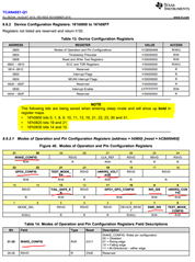
I need some help understanding what registers to check when I have an interrupt from the nINT pin.
I'm probably missing something, but here is the background:
I have successfully written a driver for this device on a different board. On that, I have no problem reading and writing CAN messages.
On a new board, which is only slightly different, and not expected to be different in the area of the TCAN4551, I have a problem that when there is a single message on the CAN bus, the nINT pin goes low to interrupt the MCU, but when I read the registers I cannot see evidence that the TCAN has received a message. this means:
As soon as I externally transmit a message on the CAN, the nINT pin goes low (so definitely message rx driven, and repeatable consistently). When the MCU firmware sees this, it reads
REG_DEV_IR = 0x000004A0
REG_MCAN_IR = 0x00010008
it seems to be setting the RF0L message lost but
REG_MCAN_RXF0S shows no messages at all, so how did I lose the message?
I can't see any indication in
REG_MCAN_ECR = 0x00000000
REG_MCAN_PSR = 0x00000708
I can't work out where the message has gone, or if there was an error, what it was. (i'm concerned there could be some kind or hardware issue on the new board affecting bit detection)
I am not using any filters, and only using RX0 elements.
What other registers should I be looking at?
At the end of my interrupt function, I clear the interrupts, and the pin goes high again until I send another message.
I think maybe it's something from the DEV IR, but I can't work out what.
Regarding which interrupts I'm enabling, it's mostly from the demo code - it behaves the same whether or not I enable the RF0L interrupt:
/* Set the interrupts we want to enable for MCAN */
TCAN4x5x_MCAN_Interrupt_Enable mcan_ie = {0}; // Remember to initialize to 0, or you'll get random garbage!
mcan_ie.RF0NE = 1; // RX FIFO 0 new message interrupt enable
mcan_ie.RF0WE = 1; // RX FIFO 0 watermark interrupt enable
mcan_ie.RF0FE = 1; // RX FIFO 0 full interrupt enable
// mcan_ie.RF0LE = 1; // RX FIFO 0 message lost interrupt enable (if on it's own doesn't mean there's a message to process)
mcan_ie.EWE = 1; // Error Warning interrupt enable
mcan_ie.BOE = 1; // Bus Off interrupt enable
TCAN4x5x_MCAN_ConfigureInterruptEnable(&mcan_ie); // Enable the appropriate registers
/* Configure the TCAN4550 Non-CAN-related functions */
TCAN4x5x_DEV_CONFIG devConfig = {0}; // Remember to initialize to 0, or you'll get random garbage!
devConfig.SWE_DIS = 0; // Keep Sleep Wake Error Enabled (it's a disable bit, not an enable)
devConfig.DEVICE_RESET = 0; // Not requesting a software reset
devConfig.WD_EN = 0; // Watchdog disabled
devConfig.nWKRQ_CONFIG = 0; // Mirror INH function (default)
devConfig.INH_DIS = 0; // INH enabled (default)
devConfig.GPIO1_GPO_CONFIG = TCAN4x5x_DEV_CONFIG_GPO1_MCAN_INT1; // MCAN nINT 1 (default)
devConfig.FAIL_SAFE_EN = 0; // Failsafe disabled (default)
devConfig.GPIO1_CONFIG = TCAN4x5x_DEV_CONFIG_GPIO1_CONFIG_GPO; // GPO1 output (default)
devConfig.WD_ACTION = TCAN4x5x_DEV_CONFIG_WDT_ACTION_nINT; // Watchdog set an interrupt (default)
devConfig.WD_BIT_RESET = 0; // Don't reset the watchdog
devConfig.nWKRQ_VOLTAGE = 0; // Set nWKRQ to internal voltage rail (default)
devConfig.GPO2_CONFIG = TCAN4x5x_DEV_CONFIG_GPO2_NO_ACTION; // GPO2 has no behavior (default)
devConfig.CLK_REF = 1; // Input crystal is a 40 MHz crystal (default)
devConfig.WAKE_CONFIG = TCAN4x5x_DEV_CONFIG_WAKE_BOTH_EDGES;// Wake pin can be triggered by either edge (default)
TCAN4x5x_Device_Configure(&devConfig); // Configure the device with the above configuration
Any pointers would be gratefully received.


