Part Number: TCA9544A
Tool/software:
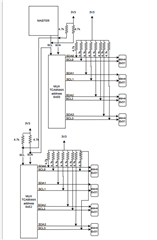
"I have developed four PCB boards and connected them through cables, with the master on one board, from where I am performing I2C communication."
"Also, a GPIO expander on one PCB board controls two 4-channel multiplexers on one board and one 4-channel multiplexer on another PCB board."
"Each channel is connected to a single I2C device."