This thread has been locked.

If you have a related question, please click the "Ask a related question" button in the top right corner. The newly created question will be automatically linked to this question.

TUSB321AI: TUSB321 configurations

Part Number: TUSB321AI
Other Parts Discussed in Thread: TUSB321, TPS2013,

Tool/software:

I am designing a system that uses the TUSB321 to figure out the high-speed lane swapping.  Data is private, and not intended to work with other USB-C systems. All voltages are in spec in case someone does connect it to a phone or laptop.

Board A:  Can supply power but will never need power. Is configured as a DRP

Board B: Will need power and is configured as a UFP


Options:
1) Board A connected to Board B.

In this configuration, the DRP port must come up as a DFP and supply 5V power to the UFP device.

2) Two Board B connected to each other. Both sides are chips in DRP and must figure out who is the DFP and who is the UFP. I really don't care, but I do need the DIR pin on either side to know how to swap the high-speed lanes. Power must not flow between these two boards, in either direction.

Board B is easy got that figured out.

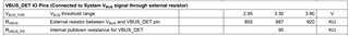
Board A is a little harder. I know how to configure the chip, but the power is the problem. This board has it's own 5V internal supply. I can power VDD from this. But I am un-sure what VBUS_DET should connect to.

And so far the only thing I can figure is to put a diode on the connector VBUS so power can only flow out of the board. But I don't like the voltage drop. Boards B will not care if the supply is a little lower, but I am un-sure if the TUSB on Board B is to low and not come up. I have looked into some PFET options, but they need to be automatic and just block current from coming into the board. So far I have not been able to figure this one out.

Any suggestions.

  • Hi Colin,

    2) Two Board B connected to each other. Both sides are chips in DRP and must figure out who is the DFP and who is the UFP. I really don't care, but I do need the DIR pin on either side to know how to swap the high-speed lanes. Power must not flow between these two boards, in either direction.
    Board B: Will need power and is configured as a UFP

    I'm not sure what you mean. Two UFP are nonfunctional if plugged into each other did you mean Board A here?

    And so far the only thing I can figure is to put a diode on the connector VBUS so power can only flow out of the board. But I don't like the voltage drop. Boards B will not care if the supply is a little lower, but I am un-sure if the TUSB on Board B is to low and not come up. I have looked into some PFET options, but they need to be automatic and just block current from coming into the board. So far I have not been able to figure this one out.

    You could gate off the voltage using a MOSFET on board A and send a manual trigger via GPIO control on the SoC to connect the 5V to when board B is plugged in, but keep the signal when board A is plugged in. Is there some identification code or register that can be read that differentiates board A and B?

    Otherwise a Diode + a boost regulator to compensate for the loss across the diode may work?

  • Yes, I did mean Board A.

    And no, no registers or anything else to know what is connector or even if someone plugged in a phone or a power brick. I have to be careful that this is compatible with configurations I did not intend. Some one is going to try it.

    The MOSFET will not work, because the SoC has no idea that Board B has been connected until it's given power. And I can't turn on power unless I know it is Board B. I mean, I guess I could keep the MOSFET on until I know it is Board A, but there would be a small window when both Board boards A could have the MOSTFET on.  And the ID pin only goes low, when a DFP port is connect, hi could mean no connection or a UFP, so I can't really use that pin. this this does not work either. 
    Yeah, I have thought of putting the Board regulator to 5.25, but I don't want to push it, There are other parts that use that regulators, that have a NE of 5.5V

    If the ID pin would go low on detecting a UFP, I could use that to turn off the power to the connector, but it does not, so, no joy...

    What about the VBUS-DET, do you know how this should be connected on Board A? The datasheet says to connect it to VBUS (w /900KOhm) but on Board A, VBUS is never not on. So will the Dual-Roll state-machine work?


    Any other idea?

  • Hmmm, nothing off the top of my head, Ill think about it further and get back to you.

    Power must not flow between these two boards, in either direction.

    Why cant power flow across here?

  • Both boards have their own 5V switching regulator. If one has a slightly (even mVs) higher voltage, current will start flowing to the the other and supplying all of it's needs. The boards are actually in a mesh, each board has 4 ports to it's neighbors. This can quickly spiral out of control with a single regulator trying to supply power to dozens of boards. Things will over load, the regulator will shut down etc... 

    This something that should never be allowed to happen.

  • Hi Colin,

    Thanks for the explanation. Just to double confirm my understanding of the issue.

    Board A: DRP and has an internally supplied 5V source, that can supply power

    Board B: UFP and needs power

    Board A -> Board B: connects as a DFP and UFP and all is good

    Board B -> Board B: Two UFPs connect without power non-functional

    Board A -> Board A: DRP configures one port to UFP and the other to DFP but Vbus cannot be transmitted across the connection?

  • Yup, For now, I guess I am just going to use the Diode and set the regulator to 5.25V

    But I still need to know about VBUS_DET. It's not clear how this should be wired with the chip configured as DRP

  • Hi Colin,

    Yes, seems like the diode and boosting the voltage may be the best solution here.

  • I have been reading a lot of messages on line, and some comments have be worried about just connecting VBUS_DET to VBUS (which will always be 5V, even at power up) Lots pf MCU's controlling stuff. I don't have that option. That is why I picked the TUSB321, because it was cheap, and did not require a MCU.

    Have you used this chip your self? Not sure your exact expertise here.

  • Hi Colin,

    VBUS_DET to VBUS (which will always be 5V, even at power up)

    Vbus will never be set until CC communications have confirmed which port will act as a DFP and UFP. Please have a look at the following FAQ which explains how to control Vbus across a type-C connector. Are you not using a Vbus switch in your design?

    FAQ: (18) [FAQ] How to control VBUS on a USB-C port - Interface forum - Interface - TI E2E support forums

    Please share a block diagram of what you're looking to do here. I'm not sure I understand what you mean by mesh here

    The boards are actually in a mesh, each board has 4 ports to it's neighbors.
  • ignore the mesh comment, it's not important to the question.

    That diagram is weird, please explain, how can the downstream device negotiate CC without power?
    The photo implies that no power should be sent to the downstream device until after the roll has been determined.


    Don't I need to send VBUS power, so the downstream TUSB321 VDD is active for the chip to be able to turn on?

  • If the TUSB321 can do the CC magic for DRP without power, then I can just use a TPS2013 for VBUS and be done. And since only DFP rolls will ever turn on the switch, then I don't need the diode from 5V to VBUS.

    Please confirm what this understaning.

  • Hi Colin,

    CC negotiation is done on the CC1 and CC2 pins. 

    A DFP will always have terminations to 3.3V or 5V through resistor Rp, or serve as a current source

    A UFP will always have terminations to ground through resistor Rd. 

    A DRP will switch between a DFP termination and UFP termination in a periodic manner.

    The negotiation is done almost instantly and the steps are closer to being performed in parallel rather than sequentially.

    1) Determine orientation of cable by seeing which CC pin is pulled to a voltage over the detection threshold. 

    These are the thresholds for all DPF terminations.

    The resistor value used are as follows:

    2) Determine the current sourcing capability on the Vbus using the resistor values on the CC pins.

    3) Supply Vbus

    This is how the CC communication works.

    If the device is unpowered without Vbus, this is called dead battery mode. In this mode the port cannot be a DRP or a DFP. It can only be a UFP. 

  • That is a lot of detail, however, it does not answer my basic question. How can the TUSB321 specifically, perform the negotiation without power. Are you trying to tell me that it has internal package resistors to ground that default to enabled even when VCC is 0V.

    As I said above, if that is true, then ID on Board A can drive a TPS2013 for VBUS and I do not need the diode. Please confirm that.

    Last question, since you called this Dead Battery Mode. Do I need to use TUSB321AI for this to all work as we are describing?

  • OK. Looking at the TUSB231AI data sheet, 7.4.3 Dead battery mode is defined as VCC = 0V, and in this mode CC pins default to 5.1K Pull down to VSS. 

    I think that about covers my questions. Thanks