Tool/software:
Hi team,
My customer want to do BER test. Seeing from test suite, I can't understand register setting to do procedure #4.
Could you please teach me how to do.

Regards,
Youhei
This thread has been locked.
If you have a related question, please click the "Ask a related question" button in the top right corner. The newly created question will be automatically linked to this question.
Tool/software:
Hi team,
My customer want to do BER test. Seeing from test suite, I can't understand register setting to do procedure #4.
Could you please teach me how to do.

Regards,
Youhei
Also teach me how to read error counter? From phy register or packet monitoring station?
Hi Youhei,
Seeing from test suite, I can't understand register setting to do procedure #4.
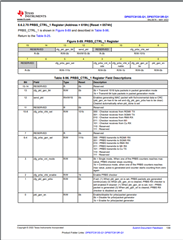
See section 8.3.1.5.1 called Data Generator and Checker in the DP83TC813x-Q1 datasheet.

Also see page 139 in the datasheet for more information.

Bit 13 will need to be 0b so that the generator generates 1,518 byte packets.
Depending on what the customer wants to see, they can view the packets on the packet monitoring station of the PHY. I have heard that it is easier to use the packet monitoring station.
Best Regards,
Nick
Hi Nick,
Thank you. Let me check some other points for this BER test;
1. Which is correct, Loopback enable or disable?
2. The PC + media converter counts bit errors, so is it OK to set the generator/checker on the cable side?
3. About description "Write register 0x0620[1] = 1'b1" in datasheet, how to write 1'b1? I can't understand this command.
4. Between master test and slave test, the only hardware setting difference is bootstrap resistor which decide Master/Slave. Is my understanding correct?
Regards,
Youhei
Hi Youhei,
1. Which is correct, Loopback enable or disable?
It seems like the customer is testing the MDI cable side so loopback can be disabled. Loopback would be if the user wanted to check the MAC side.
2. The PC + media converter counts bit errors, so is it OK to set the generator/checker on the cable side
Yes, if the user does not need the error counter then they can ignore the read and write to 0x0620 and set 0x0619[2] = 0 to disable the PRBS checker.
About description "Write register 0x0620[1] = 1'b1" in datasheet, how to write 1'b1? I can't understand this command.
My understanding is that by enabling bit 1 of the register 0x0620, the user can clear the errors to reset the error counter before beginning a test. 1'b1 means 1 binary 1. It is a notation meaning that the bit is equal to 1.
4. Between master test and slave test, the only hardware setting difference is bootstrap resistor which decide Master/Slave. Is my understanding correct?
Hardware or register value decides the configuration. One link partner must be in MDI master mode while the other is in MDI slave mode. Verify this is the case by reading register 0x1834 on both PHYs or by checking the pin strap value in the schematic.
Is the customer using the MAC interface at all?
Best regards,
Nick