This thread has been locked.

If you have a related question, please click the "Ask a related question" button in the top right corner. The newly created question will be automatically linked to this question.

DS90UB954-Q1: XIN/REFCLK clock

Part Number: DS90UB954-Q1

Tool/software:

Hi Team,

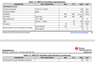
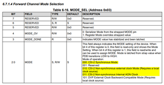
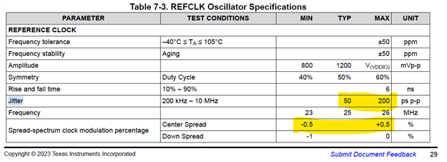
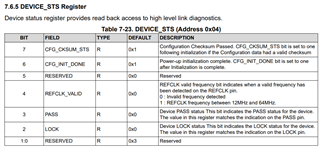
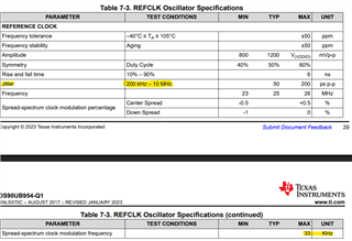
As per the datasheet of DS90UN954-Q1, it internally generates 25MHz clock initially as a backup. We are using in synchronous mode.

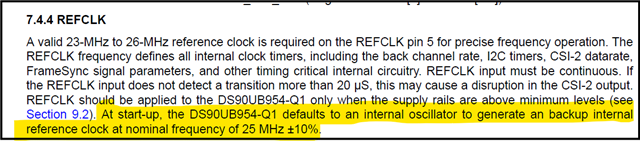
Is there a way, we can use DS90UB954-Q1 from internal oscillator only? I want to remove to external resonator.

  • Hi,

    Using reference clock for UB954 is mandatory, the oscillator must be used to provide an accurate and stable reference clock source to keep the link stable.

    Best,

    Thomas

  • Ok. Tank you

    What all clock architecture can be there between Serdes to improve EMI and EMC performance?

  • Hi Sevender,

    If EMI/EMC is a concern a reference clock with spread spectrum could be used - the spec for this oscillator can be found in the datasheet of the UB954.

    Best,

    Thomas

  • Thank you very much for your support. I am using external spread spectrum capable oscillator but still facing EMI issues.

    I want to know, is there any clock architecture between Serialiser-Deserialiser which can minimise the EMI issues?

    Thanks again

  • Hi Sevender,

    Could you please provide a summary of your ESD test results? Is this a system with a single UB954 paired with a single UB953?

    Best,

    Thomas

  • Hi Thomas,

    We are using dual camera means two UB953 and one UB954 in a complete system. 

    We are facing issues in radiated emission and getting harmonics of 100MHz and from sniffer probe we detected that UB954 clock circuitry is the main contributor for that. Can you please help me in any regards?

  • Hi Sevender,

    Could you provide more details on this? What frequency are the limits being hit? By how many dB are the limits exceeded on your syste?

    Best,

    Thomas

  • Hi Thomas,

    Please see the attached image for your reference. A small guidance will help a lot.

  • Hi Sevender,

    Have you tried options such as UB935 internal clock, or SSC oscillator providing the reference clock to the UB954?

    Any setup photos would also be appreciated.

    Best,

    Thomas

  • Hi Thomas,

    Did not get the context "UB935 internal clock", Please explain some more.

    Spread spectrum enabled oscillator we are using on the deserialiser reference clock. It is helping but not much. Any other suggestion would be appreciated.

    Thanks

  • Hi Sevender,

    Non sync AON mode is described below for override on UB935.

    Best,

    Thomas

  • Hi Thomas,

    Sorry for the late reply.

    AON mode is not applicable in our case as we are generating pixel clock for image sensor from Serialiser only. 

  • Hello Sevender,

    If you are using the clock generated by the CLK_OUT pin of the 953 to feed to the imager, then you are correct that you can't use Non-Synchronous Internal AON Clock mode.

    Are you sure that the FPD-Link devices are the source of the EMI/EMC disturbances? The spectral separation between the peaks is about 100MHz. But if you are in Synchronous Mode and using a 25MHz REFCLK at the 954, then we expect the spectral separation between peaks to be roughly 770kHz.

    If you cover the DOUT+/RIN+ traces on the PCB with copper tape and connect the copper tape to GND, does that reduce the spikes?

    Is it possible that the 25MHz oscillator is the source of the spikes? Can you use an oscillator with a lower drive strength, or add a small series resistor between the oscillator output and the DS90UB954-Q1 REFCLK pin?

    Best,

    Justin Phan

  • Hi Justin,

    Sorry for the late response.

    I am not sure that FPD link devices are the actual source for this EMI noise or not but when i am using oscillator with higher spread spectrum then I can see the improvement in the peaks amplitude. So somehow these peaks are related to deserialiser and FPD section.

    Yes I am using Synchronous Mode and using a 25MHz REFCLK at the 954, and spectral separation results I have shared. You can see those.

    "If you cover the DOUT+/RIN+ traces on the PCB with copper tape and connect the copper tape to GND, does that reduce the spikes?" : traces are very small in size and it is very tough to cover them as we have some nearby circuitry also.

    Currently I am using 10Ohm in the clock path of 25MHz, I will try by changing the value. Please let me know the suggested max allowed value in the clock path.

    Thanks

  • Hello Sevender,

    Have you confirmed that the oscillator is not the source of the EMI/EMC disturbances?

    If you pull PDB=LOW on both the serializer and deserializer and keep the oscillator powered-up, do you still see spikes that have a spectral separation of about 100MHz?

    Best,

    Justin Phan

  • Hi Justin,

    We have tried PDB low on deserialiser only, still we can see the peaks there but amplitude is less as compared to earlier.

    One more point I want to know regarding clock here is

    Allowed Jitter is 200pS but spread spectrum can support upto +-0.5%. So if I am using 25MHz SS oscillator then the freq. variation will be around 125KHz in both side.

    The total time variation across the defined time period (25MHz clk) is approx 4uSec which is quite higher than the accepted Jitter value 200pS.

    Can you please help me to understand the gap here.

  • Hello Sevender,

    1. In your EMI/EMC testing, did you also power down the 953 camera modules in addition to pulling PDB=LOW for the 954 device? I just want to make sure that only the 25MHz oscillator is active in the system when you took your before and after measurements
    2. Is there an oscillator on the 953 serializer boards?
    3. Are you able to populate a series resistor from the oscillator output to the 954 REFCLK pin?

    If the concern is whether the 954 is utilizing the input from the oscillator, then you can poll register 0x04 in the 954 device and confirm that the REFCLK_VALID bit is always set to 1.

    Best,

    Justin Phan

  • Hi Justin,

    1. As  I mentioned, I had pulled down only deserialsier PDB as I do not have any hardware control over serialiser ckt.

    As per my understanding If Deserialiser is in power down state then there will be no locking state and serialiser will not be in active state.

    2. We do not have any oscillator on serialiser side.

    3. 10 Ohm we are using already in the clock path.

    One more point I want to know regarding clock here is

    Allowed Jitter is 200pS but spread spectrum can support upto +-0.5%. So if I am using 25MHz SS oscillator then the freq. variation will be around 125KHz in both side.

    The total time variation across the defined time period (25MHz clk) is approx 400pSec which is quite higher than the accepted Jitter value 200pS.

    Can you please help me to understand the gap here.

  • Hello Sevender,

    1. If you cannot pull PDB=LOW on the 953 serializer, then the FC signal will still be active. The 953 has an internal AON clock which it will reference to generate the FC signal when the 954 is disabled. Are you able to disable PoC power to the camera module from the 954 hardware side?
      1. Main goal is to compare the EMI results when:
        1. Everything is powered up
        2. When only the 25MHz oscillator on the 954 PCB is powered-up.
    2. Let me check internally for clarification.

    Best,

    Justin Phan

  • For the oscillator jitter spec, the Test Condition is between 200kHz - 10MHz. The SSCG modulation frequency is 33kHz (max).

    If you measure the jitter of the REFCLK input in the frequency BW of 200kHz - 10MHz, then the spread spectrum modulation frequency will be excluded from the measurement.

    Customer needs to confirm separately:

    1. The jitter from the oscillator (in the BW of 200kHz - 10MHz) is 200ps pk-pk (max)
    2. The SSCG modulation percentage is within +/-0.5% Center Spread or -1% Down Spread
    3. The SSCG modulation frequency is 33kHz (max)

    All conditions can be met.

    Best,

    Justin Phan

  • Hi Justin,

    Thank you for your reply.

    What actually you mean by "If you measure the jitter of the REFCLK input in the frequency BW of 200kHz - 10MHz, then the spread spectrum modulation frequency will be excluded from the measurement".

    Is this the measurement instrument bandwidth?

    1. The SSCG modulation percentage is within +/-0.5% Center Spread or -1% Down Spread---> we are using +-0.1% center spread oscillator. see below

    2. The SSCG modulation frequency is 33kHz (max) ---> This freq. is not mentioned in the oscillator specs. I am still not clear about the impact of this freq. of modulation on Jitter.

  • Hello Sevender,

    The SSCG modulation frequency is the rate at which the clock frequency is varied. If you measure the jitter of the oscillator in the BW of 200kHz - 10MHz, then the SSCG modulation frequency should not appear in your measurement.

    It is possible to meet the jitter spec with SSCG applied, since the BW of jitter excludes the fmod of SSCG.

    1. Yes, +/-0.1% center spread is supported by our device.
    2. The modulation frequency (fmod) is typically between 30kHz - 40kHz, but you need to confirm that it is less than 33kHz in the oscillator datasheet, since our device can only support up to 33kHz modulation frequency.

    Best,

    Justin Phan