


Part Number: TCAN2451-Q1
Tool/software:
Hi team,
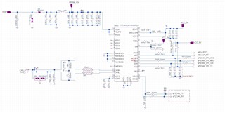
Could you please help review the schematic and give some suggestions? Thanks!
Regards,
Ivy
Part Number: TCAN2451-Q1
Tool/software:
Hi team,
Could you please help review the schematic and give some suggestions? Thanks!
Regards,
Ivy
