This thread has been locked.

If you have a related question, please click the "Ask a related question" button in the top right corner. The newly created question will be automatically linked to this question.

SN75DP130: Conditions for transitioning to Output Disable Mode

Part Number: SN75DP130

Tool/software:

Dear, support team.

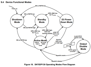
Q1. Conditions for transition to Output Disable Mode.
I understand that there are two conditions for transition to Output Disable Mode.

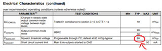
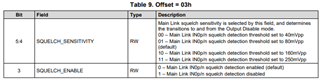
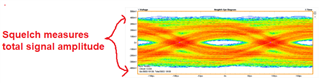
First. When a Squelch event occurs in the video signal.
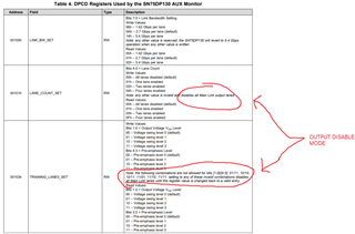
When the values ​​of DPCD registers 101h and 103h become invalid.

Second. When any of the main links 0 to 3 in use does not transmit the idle pattern and becomes disabled.

I believe that this is the condition that causes the second condition to occur.
Is my understanding correct?

Q2. Detecting Output Disable Mode.
Is there a way to check if the device state is in Output Disable Mode?

Best Regards,
Hiroaki Yuyama

  • Hi Yuyama san,

    1. Your first condition is correct. When a squelch event occurs (when the input signal is below the squelch threshold) the outputs will be disabled.

    The second condition occurs when the DCPD registers are configured with invalid settings. These can be seen in the datasheet:

    2. There is no register for this so you'd need to look at the input and output to see whether the signal is passing through the SN75DP130. Alternatively you could look at the device power draw to get a better idea of which state it is in.

    Best,

    Shane

  • Hi Shane-san,

    Thank you for your support.
    TWe at Disty have notified our customers on how to move and detect Output Disable Mode.
    If you have any additional questions that we don't know the answer to, please let us know.

    Best Regards,
    Hiroaki Yuyama
  • Hi Shane-san,

    I have a follow-up question from the same customer.

    Is it correct to think that squelch occurs when the amplitude of the MainLink input waveform in the attached diagram is attenuated at Hi?
    In that case, can the Hi detection level be changed using Table 9. Offset = 03h?

    Best Regards,
    Hiroaki Yuyama
  • Hi Yuyama-san,

    The squelch will occur when the amplitude of the main links is below the 80mVpp squelch threshold. This can result from a high-loss channel:

    Yes you can increase or decrease the squelch threshold using the SQUELCH_SENSITIVITY register:

    Best,

    Shane

  • Hi Shane-san,

    Thank you for your technical support.
    I have a follow-up question to your previous answer.

    The customer does not understand the criteria for squelch detection.
    Is it correct to assume that squelch occurs when the amplitude (H) of the MainLink input waveform in the attached diagram is reduced?
    In that case, is it between the differential inputs of InP and InN, or the differential output that has passed through the EQ?

    Best Regards,
    Hiroaki Yuyama

  • Hi Yuyama-san,

    Squelch occurs when the amplitude of the main link falls below the squelch threshold of 80mVpp (or whatever setting is in the SQUELCH_SENSITIVITY register)

    Squelch is between the differential inputs Inp/n, not the outputs.

    Are you not able to get a signal output on SN75DP130?

    Best,

    Shane

  • Hi Shane-san,

    Thank you for any advice from Shane-san.

    These are the waveforms and measurement points from the customer.
    Also, there is no termination resistor attached to the outside of the SN75DP130.

    Best Regards,
    Hiroaki Yuyama


  • Hi Yuyama-san,

    Shane-san is currently out of office and will return 3/5/2025 to answer your question.

    Also, I think you may have uploaded the different screenshot. Could you please check if the screenshot is the correct one?

    Thank you.

    Best,
    J

  • Hi J-san,

    Thank you for your reply.

    I have asked the customer for the signal output waveform requested by Shane-san,

    Please wait for their reply.

    Best Regards,
    Hiroaki Yuyama

  • Hi Yuyama-san,

    The signal you show should be enough to pass the squelch threshold on the DP130. What do you see at the output?

    Can you confirm that the device is powered and that HPD_SNK is being pulled high by your sink? If HPD_SNK is not pulled high, our device will go into a low power standby state:

    Best,

    Shane

  • Hi Shane-san,

    Thank you for any advice from you.

    We at Disty have instructed the customer to check the output waveform and the status of HPD_SNK.
    We have also instructed them to take screenshots of the output waveform.


    Best Regards,
    Hiroaki Yuyama

  • Sounds good, I'll await your response.

    Best,

    Shane

  • Hi Shane-san,

    Thank you for your advice..
    We received a reply from the customer.

    They say that the video is displayed normally at the output.
    We would like to know what you mean by "enough to pass the DP130's squelch threshold".
    The eye opening amplitude of the signal you previously sent us by email appears to be about ±40mV.
    However, we understand that the squelch detection condition is ±80mV.
    We believe that squelch detection occurs when 80mV > 40mV is met.

    Maybe the customer is misunderstanding the squelch level.
    I think it's peak-to-peak, not plus-minus.

    Best Regards,
    Hiroaki Yuyama

  • Hi Yuyama-san,

    The squelch measures based on the total signal amplitude, not on the eye opening amplitude. The signal image you sent on E2E earlier looks to have a total amplitude around 750mVpp 

    I think it's peak-to-peak, not plus-minus.

    You're correct. mVpp is short hand for millivolts peak-to-peak.

    Best,

    Shane

  • Hi Shane-san,

    Thank you for your support.

    We have discovered that our customer misunderstood Squelch's standards.
    We will close this case.

    Best Regards,
    Hiroaki Yuyama