This thread has been locked.

If you have a related question, please click the "Ask a related question" button in the top right corner. The newly created question will be automatically linked to this question.

DP83TG720S-Q1: DP83TG720EVM-MC and Custom Board with DP83TG720SWRHARQ1 – PHY Detected but No Stable Communication

Part Number: DP83TG720S-Q1

Other Parts Discussed in Thread: DP83TG720R-Q1, DP83TG720EVM-MC,

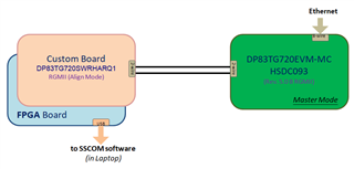
Our team is evaluating the DP83TG720R-Q1 Ethernet PHY using a custom-designed board and the DP83TG720EVM-MC evaluation board.
The setup is as follows:

  1. Evaluation Board (EVM) Connection: The DP83TG720EVM-MC is connected to Ethernet.
  2. Custom Board Setup:
    • The custom board also uses the DP83TG720R-Q1.
    • The custom board is connected to an FPGA, which serves as the MAC interface.
    • The FPGA is connected to a laptop via USB, and SSCOM software is used to monitor communication.
  3. PHY ID Recognition:
    • The PHY is correctly detected in SSCOM, meaning the MDIO interface is working.It gives following msg:

      Configuring network interfaces...ZYNQ GEM: ff0e0000, mdio bus ff0e0000, phyaddr 0, interface rgmii-id
      [17:32:49.368]IN¡û¡ô[ 7.669787] macb ff0e0000.ethernet eth0: PHY [ff0e0000.ethernet-ffffffff:00] driver [TI DP83TG720CS1.1] (irq=POLL)
      [ 7.680170] macb ff0e0000.ethernet eth0: configuring for phy/rgmii-id link mode

    • However, communication does not happen, or if it does, it lasts for a very short time (~10 sec).
  4. Error Message in SSCOM:
  •  [17:34:17.463] IN¡û¡ô [100.874880] macb ff0e0000.ethernet eth0: Link is Up - 1Gbps/Full - flow control off
  • [17:34:27.681] IN¡û¡ô [105.994103] macb ff0e0000.ethernet eth0: Link is Down

          This suggests that the link is initially established but drops shortly after.

TROUBLESHOOTING done so far:

Heavy check mark Clock Signal Verified

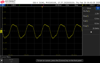
  • The 25 MHz XTAL/Clock source has been checked for correct frequency, rise/fall times, load capacitance, and impedance matching.

Heavy check mark PHY Address Identified

  • The PHY ID is detected correctly via MDIO.

Heavy check mark  MDIO Communication Checked

  • The FPGA successfully reads the PHY ID, confirming that MDIO and MDC signals are working, Isn’t it ?

Heavy check mark Power and Voltage Levels Checked

  • Verified that VDDIO(1.8V), VDDA3P3, and VDD1P0 are within the recommended range.

Heavy check mark  Strapping Pins and Configuration Verified

  • Ensured correct bootstrap settings for PHY operation. I can also try other configuration if you have any other suggestion?

Heavy check mark Termination Resistors Verified

  • Confirmed that 100Ω differential termination is present between TRD_P and TRD_M.

-

QUESTIONS for TI Support Team:

Heavy check mark Measured DC Voltage on TRD_P and TRD_M

  • Found 1.65V instead of the expected ~1.1V, suggesting a potential issue with signal integrity.

Heavy check mark PHY Link Stability Issue Observed

  • The link is established but drops after ~10 seconds, as seen in the SSCOM log.
  1. Why does the link establish briefly (~10 sec) and then drop? 
  2. Is a DC voltage of 1.65V on TRD_P/TRD_M abnormal? If so, what could be causing it?
  3. Could impedance mismatch or termination affect long-term link stability, even if the link initially establishes?
  4. Do we have to connect RESET_N and WAKE pin all the time to 1.8V and 3.3V respectively?
  5. Could this issue be related to FPGA MAC configuration? Are there specific settings needed for proper MAC-PHY interaction?

 DP83TG720_Custom Board.pdf

I have attached the schematic for your reference.
We would appreciate any insights or debugging suggestions from TI.
THANK YOU !

  • Hi Somnath,

    Thanks for sharing details on this case.

    We have several questions:

    • Does it repeatedly link up/down?  Or just single link up/down on POR?
    • What is basis for expecting 1.1V?  How are you measuring DC voltage?
    • Have you performed PMA compliance?  This would help verify if there are signal integrity issues.
    • Are you able to perform MDIO read/write once link is down?
    • When link is down, can you measure and confirm that INH / RESET high?

    Regarding your questions:

    1. It is not immediately clear why this is happening.
    2. Can you measure DC voltage on the EVM?
    3. We would expect mismatch/termination to have an impact throughout the operation of the link.  For signal integrity issue, we would expect multiple link up/link down, or packet loss.
    4. No, the internal pullup/pulldown should be sufficient assuming there is no external bias.
    5. We don't expect MDI linkup to be dependent on MII configuration.

    Thanks,

    Drew

  • Hi Drew,

    Thank you so much for your prompt response and support.

    We wanted to update you that we have sent out a new version of our PCB, as we suspect a layout issue may be contributing to the problem.
    Once the new PCB arrives, we will conduct further testing including your suggestions and share our findings with you. 
    We truly appreciate your patience and continued support. I hope to reconnect with you once we have more data.

    Please stay in touch, and I’ll reach out again when we are ready for the next steps.

    Somnath


  • Hi Somnath,

    Thanks for the update.  Looking forward to seeing how your new PCB version performs.

    Thanks,

    Drew

  • Hi Drew,

    Thank you again for your continued support.

    Since our new PCB will take at least couple of weeks to arrive, I have resumed debugging the current board, as our company needs to resolve this issue as soon as possible. In the meantime, here are our answers to your questions and our latest findings:

    1. Does it repeatedly link up/down? Or just a single link up/down on POR?

                     White check mark Yes, the link repeatedly cycles up/down until we power off the board.

                         Note: We have replaced the XTAL with a more stable and higher-quality crystal. As a result, the link no longer stays up for only 10 seconds but now continues to repeatedly cycle up and down until the board is powered off.

    1. What is the basis for expecting 1.1V? How are you measuring DC voltage?
    • According to IEEE 802.3bp (1000BASE-T1), the expected MDI common-mode voltage should be ~1.1V.
    • We measured 1.65V DC on TRD_P / TRD_M using a multimeter in DC mode while the link was idle.
    • Measured values on the EVM board:
      • TRD_P = 1.642V
      • TRD_M = 1.669V
      • Since these values match between the custom board and the EVM, we would like confirmation from TI on whether these are expected values.
    1. Have you performed PMA compliance?

                      X Not yet.
                      Question How can we perform PMA compliance testing? Any guidance or recommended test procedures would be highly appreciated.

    1. Are you able to perform MDIO read/write once the link is down?
    • We haven't run the full program yet—right now, we are focusing on hardware-level testing.
    • The issue we are experiencing is that communication is unstable, preventing further functional tests.
    1. When the link is down, can you measure and confirm that INH / RESET are high?

                    White check mark Yes, both RESET_N and INH are high when the link goes down.

    Next Steps & Further Assistance Needed

    • Could you confirm whether 1.65V DC on TRD_P/TRD_M is an expected voltage level for this PHY?
    • Can you provide guidance on PMA compliance testing?
    • Since the link repeatedly cycles up/down, what could be the likely root causes based on past debugging experiences?

    We truly appreciate your insights and assistance. Looking forward to your guidance!

    Best regards,
    Somnath


  • Hi Somnath,

    Today (Feb 17) is a holiday in the US, so responses will be delayed. Drew will get back to you shortly regarding your inquiry.

    Best,

    David

  • Hi Somnath,

    1. I can measure this on my side.  However, if you observe the same on the custom board and EVM, this is likely the correct behavior.  Also, the interface is AC coupled, so common mode should not impact the link partner.
      I looked at 802.3bp and couldn't locate the specification for common mode voltage.  Could you help point this out to me?
    2. You can look at the PMA test document on the Open Alliance website for details on the test setup.
      Test modes and associated register writes are also covered in DP83TG720S-Q1 data sheet, under `7.3.2 Compliance Test Modes`.
    3. Please allow me to discuss with my team and follow up with you on this.

    Thanks,

    Drew

  • Hi Drew,

    Thank you for your patience and support.

    1. Regarding Common-Mode Voltage:

      • After reviewing IEEE 802.3bp, we also could not find a specific specification for common-mode voltage in the standard. Sorry for the previous confusion.
      • Previously, I referenced 1.1V based on general industry expectations, but I now understand that the PHY operates in an AC-coupled environment, where common-mode voltage should not impact the link partner.
      • Our measured values (~1.65V on both the custom board and EVM) are consistent, likely the correct behaviour.
    2. PMA Compliance Testing:

      • We will check the Open Alliance PMA test document and the DP83TG720R-Q1 datasheet, Section 7.3.2 to prepare for compliance testing.
      • and try to perform the PMA compliance testing.
    3. Next Steps:

      • Awaiting further insights from your internal discussion.

    Thank you again for your support. Looking forward to your feedback!

    Regards,
    Somnath.

  • Hi Somnath,

    We suspect this may be related to an oscillator issue.  Have you confirmed the capacitor values with your crystal supplier?

    Can you probe XO and observe how long it takes to become stable from power on?

    Please share any relevant scope captures.


    Also, do you have multiple boards?  If so, do you observe the same behavior across these boards?

    Thanks,

    Drew

  • Hi Drew,

    Thank you for your suggestions. We have conducted the following tests based on your recommendations:

    1. XTAL Capacitor Verification:

      • We have confirmed that our oscillator (CX3225SB25000D0FFFCC) requires a C_L range of 6pF–10pF, and we are using capacitors that match this specification.
    2. Oscillator Stability (XO Pin Scope Measurement):

      • The oscillator stabilizes instantly upon power-up.
      • We have attached a scope capture of the XO pin for your reference, the measured value is also shown in the scope reading.          
      •    
    3. Multiple Board Testing:

      • We have tested multiple boards, and the same link instability issue persists across all of them.

    I think, the oscillator seems to be functioning correctly, what do you think?

    we would appreciate your guidance on what to check next.

    Best regards,

    Somnath

  • Hi Somnath,

    Thanks for investigating this.

    • Is it also possible to probe clkout?
    • Are you able to share more details about the layout issue that you suspect may be causing an issue?
    • Can you confirm that you're writing the Open Alliance configuration script?
      https://www.ti.com/lit/an/snla371b/snla371b.pdf
    • We also noticed that you're using the CMC recommended for DP83TC818.  Can you try the CMC recommended for DP83TG720, DLW32MH101XT2?
    • If you reset the PHY using RESET pin, do you observe the same behavior?

    Thanks,

    Drew

  • Hello Drew,

    Sorry for the late reply.

    After receiving the new PCB, we encountered the same issue, confirming that it wasn’t related to the layout or XTAL.

    After brainstorming with my senior, we discovered that the 12V to 5V LDO wasn’t supplying enough current, which in turn caused the 3.3V, 1.8V and 1V LDOs to provide "insufficient current" to the chip.

    Just wanted to update you—thanks for all your support! The issue is now resolved.

    Best Regards,
    Somnath.

  • Hi Somnath,

    Thanks for the update!  Glad to hear that you figured out the issue.

    Thanks,

    Drew