This thread has been locked.

If you have a related question, please click the "Ask a related question" button in the top right corner. The newly created question will be automatically linked to this question.

DS320PR810: schematic review

Part Number: DS320PR810

Tool/software:

Hi,

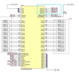
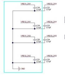
Would you please hlep us review the DS320PR810 circuit?

we use pin mode & slave mode, not support power down.

PEGASUS M8 CONTROLLER_A3_20250210-DS320PR810 (1).pdf

Thanks!

Jeff

  • Hi Jeff,

    Please find my schematic review comments below. The comments which highlight potential problems or clarifications are in bold.

    • MODE: 1k to GND for Pin Mode (ok). Options for SMBus Primary and Secondary modes as well.
    • ALL_DONE_N: Floating (ok). Option for 4.7k pull-up to 3.3V for SMBus modes.
    • READ_EN_N: Floating (ok)
    • EQ0_0 / ADDR0: Strapped 75k to GND for L3
    • EQ1_0 / ADDR1: Strapped 75k to GND for L3
      • Combined with EQ0_0, this sets channel 0-3 EQ Index to 18. Please note that this EQ Index is quite high, is this the desired EQ setting?
    • EQ0_1Strapped 75k to GND for L3
    • EQ1_1: Strapped 75k to GND for L3
      • Combined with EQ0_1, this sets channel 4-7 EQ Index to 18. Please note that this EQ Index is quite high, is this the desired EQ setting?
    • GAIN0 / SDA: Pulled up with 4.7k to 3.3V.
      • Please keep GAIN0 strapped to a valid L0-L4 strap level if using Pin Mode. Currently, it is pulled-up to 3.3V, which is a strap I would expect in SMBus modes. Recommend to de-pop R571 for Pin Mode to disconnect I2C bus.
    • RX_DET / SCL: Pulled up with 4.7k to 3.3V and pulled down to L1 using 8.2k to GND (R699)
      • Please keep RX_DET strapped to a valid L0-L4 strap level if using Pin Mode. Currently, it is pulled-up to 3.3V, which is a strap I would expect in SMBus modes. Recommend to de-pop R570 for Pin Mode to disconnect I2C bus.
    • GAIN1: Floating for 0dB Flat Gain (ok)
    • PD0 / PD1: Strapped to GND (ok)
      • Please note data sheet comment regarding RX Detect in PCIe applications:
        • In PCIe applications PD0/1 pins can be connected to PCIe sideband signals PERST# with inverted polarity or one or more appropriate PRSNTx# signals to achieve desired RX detect functionality.
    • RSVD0 / 1: 0.1uF de-coupling capacitor to GND on each
      • Per data sheet guidelines, please keep these pins floating (NC).
    • RXnN / P: Connected to GFX_TXn+/-, which are AC coupled with 220nF capacitors (ok).
    • TXnN / P: Connected to PCIe_SLOT8X_HTDRn+/- lines
      • Please ensure that these PCIe channels are AC coupled, as this is not shown in the provided schematic. Recommended AC coupling capacitor value is 220nF.
    • VCC: Connected to de-coupling network of 1x 10uF and 4x 0.1uF.
      • Note one 1uF bulk capacitor per device is recommended in data sheet Section 9.
    • GND: Connected to GND (ok)
    • RSVD2 / 3 / 4 / 50.1uF de-coupling capacitor to GND on each
      • Per data sheet guidelines, recommend 0 Ohm to GND on each for best signal integrity performance.

    Please let me know if you or the customer have any questions or comments.

    Additionally, could you please let me know the end customer and the use in this application?

    Best,
    David 

  • Hi David,

    Thank you, it is for external storage. 

  • Hi David,

    • EQ1_0 / ADDR1: Strapped 75k to GND for L3
      • Combined with EQ0_0, this sets channel 0-3 EQ Index to 18. Please note that this EQ Index is quite high, is this the desired EQ setting?

    ( I change Default value to EQ=13dB, after redriver the connector & traces insolt  loss about 7.5 dB, is ok?)

    •         RSVD2 / 3 / 4 / 5: 0.1uF de-coupling capacitor to GND on each
      • Per data sheet guidelines, recommend 0 Ohm to GND on each for best signal integrity performance.
    • From  DS320PR810-RSC-EVM User's Guide, the RSVD2 / 3 / 4 / 5 with 0.1uF de-coupling capacitor to GND on each , could you help to check it?

    Thanks!

    Jeff

  • Hi Jeff,

    ( I change Default value to EQ=13dB, after redriver the connector & traces insolt  loss about 7.5 dB, is ok?)
    • I believe this EQ gain is an OK starting point (EQ Index 8). Typically, it is recommended to provide enough CTLE gain to account for pre-channel insertion loss (before the redriver's RX pins). Here is an application note which discusses redriver tuning in detail.
    From  DS320PR810-RSC-EVM User's Guide, the RSVD2 / 3 / 4 / 5 with 0.1uF de-coupling capacitor to GND on each , could you help to check it?
    • This was based on an older recommendation. Please refer to this E2E post for some explanation.

    Best,
    David

  • Hi David,

    Thanks for your support.

  • No problem, thank you for supporting the customer.

    Best,

    Lucas