This thread has been locked.

If you have a related question, please click the "Ask a related question" button in the top right corner. The newly created question will be automatically linked to this question.

DP83848C: A specific description about "VTPTD_100"

Part Number: DP83848C

Tool/software:

Hi,all

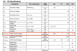
I have some questions about the VTPTD_100  in the datasheet. I wonder whether it represents the peak-to-peak value of the differential signal, or the amplitude of the single-ended signal against 0V. Can someone help me?

  • Hi, 

    This voltage refers to the amplitude of each single ended signal. The peak to peak signal would be expected to range from roughly -1V to 1V, for a total of 2Vpp. 

    Best,

    Vivaan

  • Hi, Vivaan

    Thanks for your answer. That's what I understood at first. However, I still have a question.

    https://www.ti.com/lit/an/snla088a/snla088a.pdf

    Figure 3 shows the Sample 100 Mb/s Waveform and why the peak to peak signal range is roughly -0.5V to 0.5V? I look forward to your answer.

    Best,

    Jacob

  • Hi Jacob, 

    The upper waveforms showing the 0.5V amplitude are single ended measurements. The 2Vpp refers to the differential signal. The waveform below it shows the actual differential signal using the oscilloscope math function. We can see at the bottom that the voltage per division for this math channel M1 is 1V/div, which makes the signal 2Vpp.

    This math function is simply subtracting the lower single ended signal from the upper single ended signal to create the differential pair signaling. For the positive parts of the signal, we can see it would mean something like +0.5 - ( -0.5) which gives the signal an upper bound of +1V, while for negative parts of the signal it yields ( -0.5) - 0.5 which gives the signal a lower bound of -1V. 

    I hope this clears up the confusion. Let me know if you have any other questions.

    Best,

    Vivaan