This thread has been locked.

If you have a related question, please click the "Ask a related question" button in the top right corner. The newly created question will be automatically linked to this question.

SN65DSI84-Q1: SN65DSI84-Q1 Output Related Inquiry

Part Number: SN65DSI84-Q1
Other Parts Discussed in Thread: SN65DSI84

Tool/software:

Hi, TI expert

A customer has a question regarding the SN65DSI84-Q1 output.

- Application : Video splitter and channel display device

The current hardware configuration is as follows.

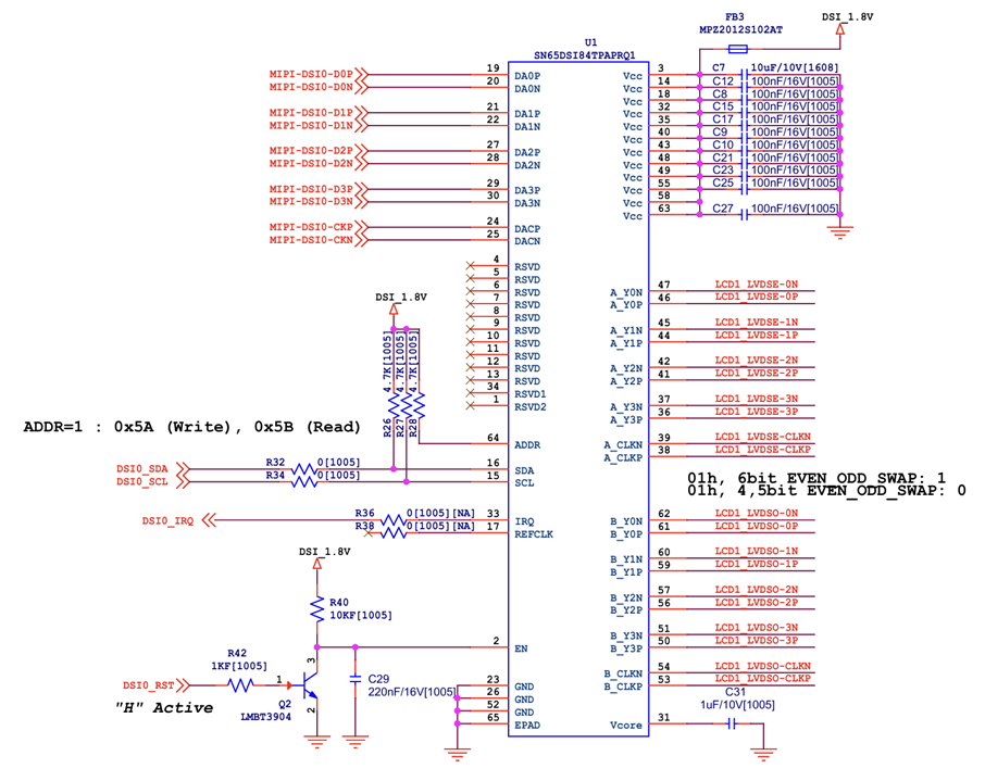
- RK3568 DSI Output (Single) -> SN65DSI84TPAPRQ1 (Dual LVDS Output) -> LCD PANEL (resolution 1920x360)

[Review and Issues]

1) When RK3568 DSI Output is set to 1920x1080, the screen is displayed normally on the LCD PANEL. (However, only the top 1/3 of the 1080 screen is displayed.)

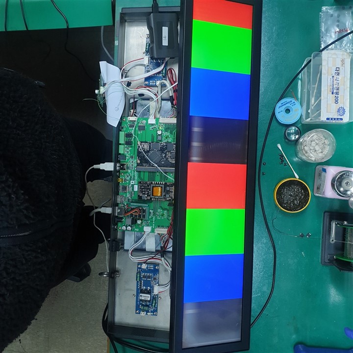
2) When RK3568 DSI Output is set to 1920x360, the LCD screen is displayed abnormally (Please refer to the image below.)

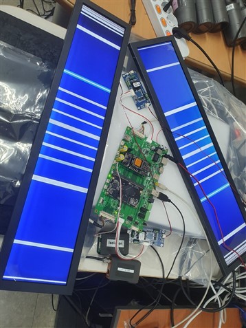
The video display timing is as follows, and the SN65DSI84TPAPRQ1 setting value is attached.

clock-frequency = <142380000>;

hactive = <1920>;

hfront-porch = <60>;

hsync-len = <60>;

hback-porch = <60>;

vactive = <360>;

vfront-porch = <120>;

vsync-len = <530>;

vback-porch = <120>;

hsync-active = <0>;

vsync-active = <0>;

[Question]

Q1) Does SN65DSI84TPAPRQ1 not support 1920x360 resolution LCD?

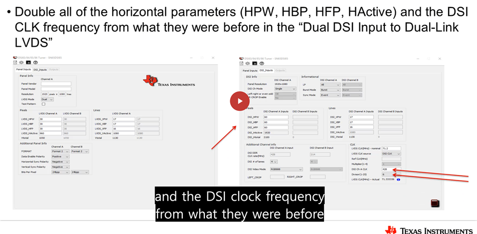
Q2) If it is supported, how can I set it up to output normally? (Currently, the SN65DSI84TPAPRQ1 IC setting was done using the software tool provided by TI.)

Please check. Thank you.

  • Hi,

    Would you please share the DSI84-Q1 schematic and register dump? 

    Are they using DSICLK or REFCLK as the clock source and what is the clock frequency they are using?

    If they enable the DSI84 internal test pattern, do they see the same issue?

    Thanks
    David

  • Hi, David

    Thank for response.

    Here is the answer to your request:

    1) Would you please share the DSI84-Q1 schematic and register dump? 

    [Schematic]

    [Register dump when setting 1920x360]

    [00]35 38 49 53 44 20 20 20

    [08]01 00 85 28 00 01 00 00

    [10]26 00 56 00 00 00 00 00

    [18]6C 05 43 00 00 00 00 00

    [20]80 07 00 00 68 01 00 00

    [28]21 00 00 00 1E 00 00 00

    [30]12 02 00 00 1E 00 78 00

    [38]3C 00 78 00 00 00 00 00

    [40]00 00 00 00 00 00 00 00

    [48]00 00 00 00 00 00 00 00

    [50]00 00 00 00 00 00 00 00

    [58]00 00 00 00 00 00 00 00

    [60]00 00 00 00 00 00 00 00

    [68]00 00 00 00 00 00 00 00

    [70]00 00 00 00 00 00 00 00

    [78]00 00 00 00 00 00 00 00

    [80]00 00 00 00 00 00 00 00

    [88]00 00 00 00 00 00 00 00

    [90]00 00 00 00 00 00 00 00

    [98]00 00 00 00 00 00 00 00

    [A0]00 00 00 00 00 00 00 00

    [A8]00 00 00 00 00 00 00 00

    [B0]00 00 00 00 00 00 00 00

    [B8]00 00 00 00 00 00 00 00

    [C0]00 00 00 00 00 00 00 00

    [C8]00 00 00 00 00 00 00 00

    [D0]00 00 00 00 00 00 00 00

    [D8]00 00 00 00 00 00 00 00

    [E0]00 00 00 00 00 00 00 00

    [E8]00 00 00 00 00 00 00 00

    [F0]00 00 00 00 40 00 00 80

    [F8]00 00 00 00 00 00 00 00

    2) Are they using DSICLK or REFCLK as the clock source and what is the clock frequency they are using?

    →  Clock Source : DSICLK

         Clock Frequency : 427.14MHz

    3) If they enable the DSI84 internal test pattern, do they see the same issue?

    → [Captured picture]

    Please check. Thank you.

  • Hi,

    Since you are using the DSI84-Q1 to support dual LVDS, we need to take into the account that there are 2 output clocks now instead of 1, and both clocks need to be taken into consideration for the DSI CLK since the DSI CLK will need to support both. So the equation is:

    With LVDS CLK = 142.38MHz, and bpp = 24 bit, DSI CLK = 854.28MHz, which is outside of the DSI84-Q1 supported range. 

    Any chance you can switch from DSI84-Q1 to DSI85-Q1 for this design?

    Thanks

    David

  • Hi, David

    The customer said that the LVDS CLK is 71.19MHz, not 142.38MHz, because it is connected to the LCD Panel using Dual Link LVDS.

    The LVDS CLK frequency was confirmed with an oscilloscope.

    The SN65DSI84 settings were referenced from the TI Youtube video as shown in the figure below.

  • Hi,

    Can they please measure the line time at the DSI input and the line time at the LVDS output? The line time from the DSI input must match with the line time at the LVDS output. Please see this E2E FAQ link, https://e2e.ti.com/support/interface-group/interface/f/interface-forum/852871/faq-sn65dsi84-no-display-output-with-sn65dsi83-sn65dsi84-sn65dsi85, for how to measure the line time.

    Thanks

    David