Tool/software:
Dear Experts,
I am working on an FPD-Link III camera system using the following configuration:
- Host: RK3588 (I2C7 as master)
- Deserializer: DS90UB954 (I2C slave address: 0x30)
- Serializer: DS90UB953 (I2C slave addresses: 0x18/0x19) (2 camera)
- Operating Mode: CSI-2 Non-Synchronous Back Channel Mode
Issue Description:
During initialization, the DS90UB953 serializer fails to configure properly. Key observations include:
- Driver Initialization Failure: The DS90UB953 initialization sequence does not complete, and the device ID (e.g., register
0x00) cannot be reliably read. - I2C Address Instability:
i2cdetect -y 7intermittently shows addresses 0x18 and 0x19 (sometimes marked asUU, sometimes missing).- Direct register access via
i2cgetresults in sporadic errors (Error: Read failed).
- Link Quality Issues: The FPD-Link III connection exhibits frequent synchronization drops (observed via
dmesglogs).
Attached Data:
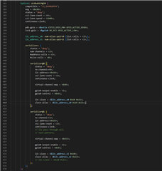
- Device tree configuration snippets (I2C alias definitions, clock settings).
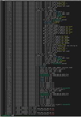
dmesglogs showing repeated timeout errors during initialization.
Request for Guidance:
Could you provide insights into the following?
- Device Tree Best Practices:
- Proper configuration of
slave-aliasentries for dual-serailizer setups. - Recommended I2C bus settings (clock frequency, noise filters) for RK3588 compatibility.
- Proper configuration of
- Non-Synchronous Mode Pitfalls:
- Critical timing requirements for CSI-2 back channel initialization.
- Known issues with clock stretching or ACK/NACK handling in this mode.
- Signal Integrity Validation:
- Key parameters to measure for FPD-Link III stability.
- Debugging steps to isolate I2C vs. link-layer faults.
Thank you for your expertise and support.
Best regards,
qing
jinanhauxiangxinxikejiyouxiangongsi