This thread has been locked.

If you have a related question, please click the "Ask a related question" button in the top right corner. The newly created question will be automatically linked to this question.

TCAN4550: PCB Trace impedance

Part Number: TCAN4550

Tool/software:

Hi team. 

As you know, there is 120Ohms termination resistor for CAN and we need to use a single twisted pair cable (shielded or unshielded) with 120 Ω characteristic impedance (ZO). So do we need to make the PCB trace impedance also 120 Ω characteristic impedance? 
  • Hi Naizeng,

    The CAN bus will act as a transmission line which is why controlled impedance matching between the signal media (twisted pair wires and PCB traces) and the termination resistance is important.  Theoretically if the impedance is the same for all elements in the transmission line, there will not be any signal reflections and the signal integrity will be optimal. If any of the elements have a different impedance, some of the signal's energy will be reflected as it passes by the element that has a different impedance.  The amount of energy reflected will be proportional to the difference in the impedance values for the elements.  So yes, it is important to try to match the impedance of the PCB traces on the CAN bus if possible. 

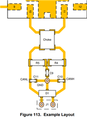
    However, this can be difficult on a PCB with additional components such as filter caps, TVS diodes, termination resistors, common mode chokes, connector pins, etc.  A differential pair routed with a 120 ohm impedance is not typically possible due to the discontinuity created by these additional components.  Therefore it is also common to see two equally routed traces that have a single-ended impedance of 60 ohms that make it easier to route through all of these components between the PCB connector and the transceiver CANH and CANL pins, and minimize the impact of the discontinuities created by the extra components themselves.

    Typical PCB trace impedance for manufacturers is 50 ohms, which is pretty close to 60 ohms.  The CAN bus standard also defines a tolerance range for the bus characteristic impedance, so perfect impedance matching is not possible.  It is important to keep the PCB traces as short as possible to that the overall impedance difference is treated as a "lumped" discontinuity on the larger CAN bus as compared to a series of smaller lumped discontinuities that will each contribute their own reflections.

    Regards,

    Jonathan