This thread has been locked.

If you have a related question, please click the "Ask a related question" button in the top right corner. The newly created question will be automatically linked to this question.

TCA9535: TCA9535 button readout via i2c interface.

Part Number: TCA9535


Tool/software:

Dear all;
We are using the TCA9535PWR chip in our equipment and we have had some problems with these chips burning out on some pins.
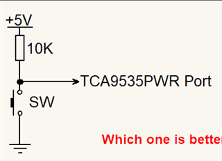
The schematic we are using is below.
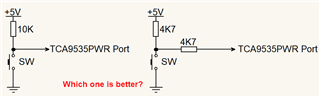
Could the way the switch is connected when we bring it to zero contribute to this (shorting to GND)? In other words, should the zero also be connected to a resistor? What is the best configuration for connecting the keys?

TCA9535 button readout via i2c interface schematic.

  • If I had to guess, I would suspect ESD damage. I do not know what ESD protection you're using. Can you show an oscilloscope trace of an ESD test (or just touching the button while charged)?

    In theory, a series resistor indeed reduces the current that can show up at the input pin. The TCA9535 does not have clamping diodes to VCC, so it might help to add them.

  • Thanks Clemens Ladisch for the feedback. I'll put the oscilloscope and my finger on it later (I can't generate the ESD here).
    On our board there is a TVS as shown below whose part number is : PESD5V0R1BSFYL.
    Is it not enough? Or should it be unidirectional? Or should it have a resistor in series with the port pin?
    In an external laboratory test, this equipment passed the ESD tests, but there was no one pressing the button and it had the pullup connected.
    Thank you in advance for any comments.
    Sincerely;
    Mauricio.

  • Hi Mauricio,

    This configuration of the SW could be problematic if the TCA9535 is coded incorrectly. If the Pxx pin is configured accidentally to an OUTPUT HIGH, then you have a direct short to GND when you press the SW. 

    Adding the series resistance (4.7k might be too much), would help to limit the current in case this were to occur. 

    If chips are burning up, it could be due to PWR - GND shorts via the OUTPUTs from the IO expander itself, or as to Clemens' concern with ESD damage from the switch. The fast change in voltage probably induces a fast change in current, which is possibly stressing the pin. 5V to GND is a big jump, and the current is not limited to the TCA9535 input pin. 

    Input capacitance would help to slow this transition down, adding of external ESD protection circuitry on the IO would help. It looks like external ESD is already provided however. 

    You could measure the ICC current through the device at the VCC pin. If you see substantial current in the 10's of mA, it might me you have a short somewhere. 

    If the current through ICC is relatively small at the DC measurement,. then maybe this issue is an AC issue (switching inputs). 

    Regards,

    Tyler

  • The actual signal cannot go below GND, so you should use a unidirectional ESD protection diode here.

    You have VCC near the buttons, so using two plain silicon diodes (e.g., BAV99) to clamp to GND and VCC would also work.

  • Thank you Tyler and Clemens for your comments.
    We'll look into them.
    I'll also try to find a unidirectional TVS to put on the existing board and test it.
    Sincerely;
    Mauricio.

  • Hi Mauricio,

    Please let us know your findings. 

    Regards,

    Tyler